Rolling freedom revolution stop mechanism for helicopter dynamic flight simulator

A stop mechanism and dynamic flight technology, applied in simulators, simulators of space navigation conditions, instruments, etc., can solve problems such as insufficient motor braking torque, potential safety hazards, and drop accidents, and achieve the purpose of overcoming the lack of motor braking torque , Ensure the safety of the machine and prevent the effect of relative rotation

Active Publication Date: 2018-12-07
GENERAL ENG RES INST CHINA ACAD OF ENG PHYSICS
View PDF23 Cites 0 Cited by
  • Summary
  • Abstract
  • Description
  • Claims
  • Application Information

AI Technical Summary

Problems solved by technology

Using the motor and reducer drive of shelf products can greatly reduce the product cost, but the braking torque of the motor is insufficient. When the pilot boards the plane, there may be relative motion between the roll frame and the yaw frame, which may cause a fall accident, safety hazard

Method used


Image

  • Rolling freedom revolution stop mechanism for helicopter dynamic flight simulator
  • Rolling freedom revolution stop mechanism for helicopter dynamic flight simulator
  • Rolling freedom revolution stop mechanism for helicopter dynamic flight simulator

Examples


Embodiment 1

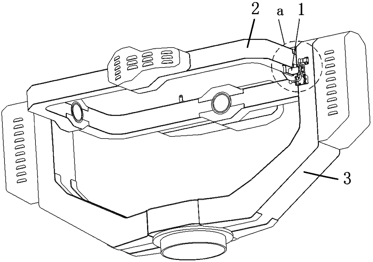
[0041] Example 1, such as figure 1 and figure 2 Shown:

[0042] The rotary stop mechanism for the rolling degree of freedom used in the helicopter dynamic flight simulator includes multiple sets of rotary stop mechanisms 1, and each set of rotary stop mechanisms 1 includes:

[0043] Rotatably connected to the deadbolt 13 installed on the yaw frame 3;

[0044] Fixedly installed on the roll frame 2 is a lock 111 that matches the size of the lock tongue 13; the lock tongue 13 snaps into the lock 111 to lock the position of the yaw frame 3 and the roll frame 2 at this time; the lock tongue 13 is disengaged When the buckle 111 is locked, the yaw frame 3 and the roll frame 2 can rotate relative to each other.

[0045]When the equipment is stationary, the rolling frame 2 and the yaw frame 3 can be locked by locking the tongue 13 into the buckle 111 to prevent the relative rotation of the rolling frame 2 and the yaw frame 3, overcome the shortcoming of insufficient braking torque ...

Embodiment 2

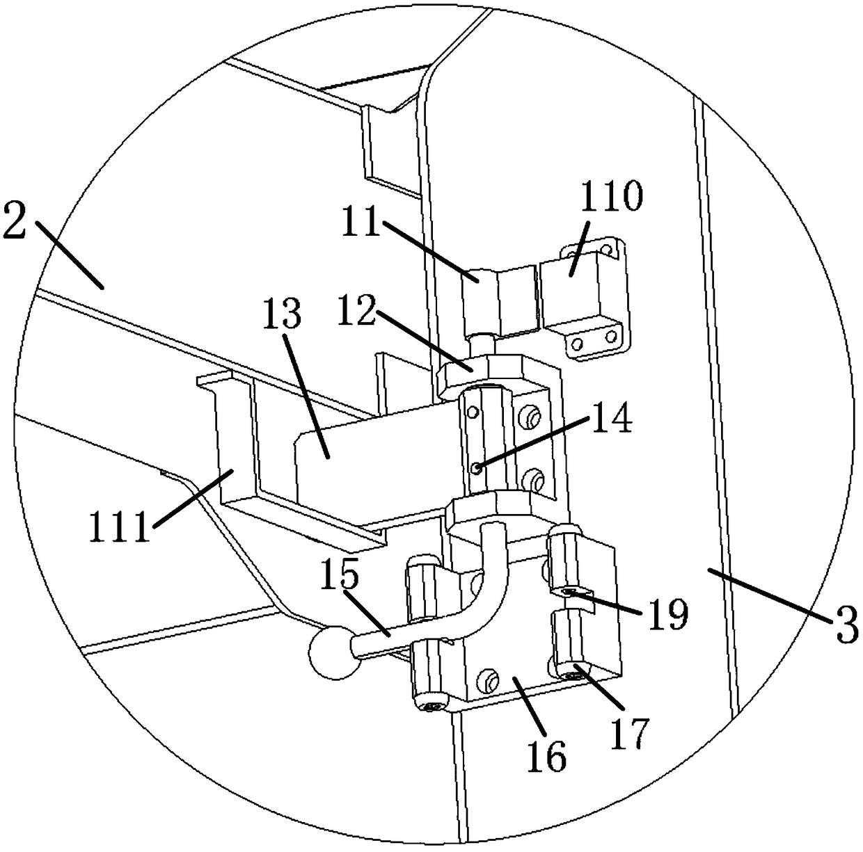
[0046] Example 2, such as figure 2 and image 3 Shown:

[0047] The difference between this embodiment and Embodiment 1 is that each group of rotation stop mechanism 1 also includes:

[0048] The rotating base 12; the rotating base 12 is a U-shaped structure, the bottom end of the rotating base 12 is fixed on the yaw frame 3, and the side wall of the rotating base 12 is provided with two opposite through holes;

[0049] Rotating shaft 15; the rotating shaft 15 has an L-shaped structure, the first end of the rotating shaft 15 passes through a through hole, the first end of the lock tongue 13 and the other through hole in turn, and the second end of the lock tongue 13 is used to match the lock buckle 111 For locking, the first end of the deadbolt 13 is placed in the notch of the rotating base 12 , and the first end of the deadbolt 13 is fixedly connected to the rotating shaft 15 through a plurality of pins 14 .

[0050] The setting of rotating base 12 can be convenient for t...

Embodiment 3

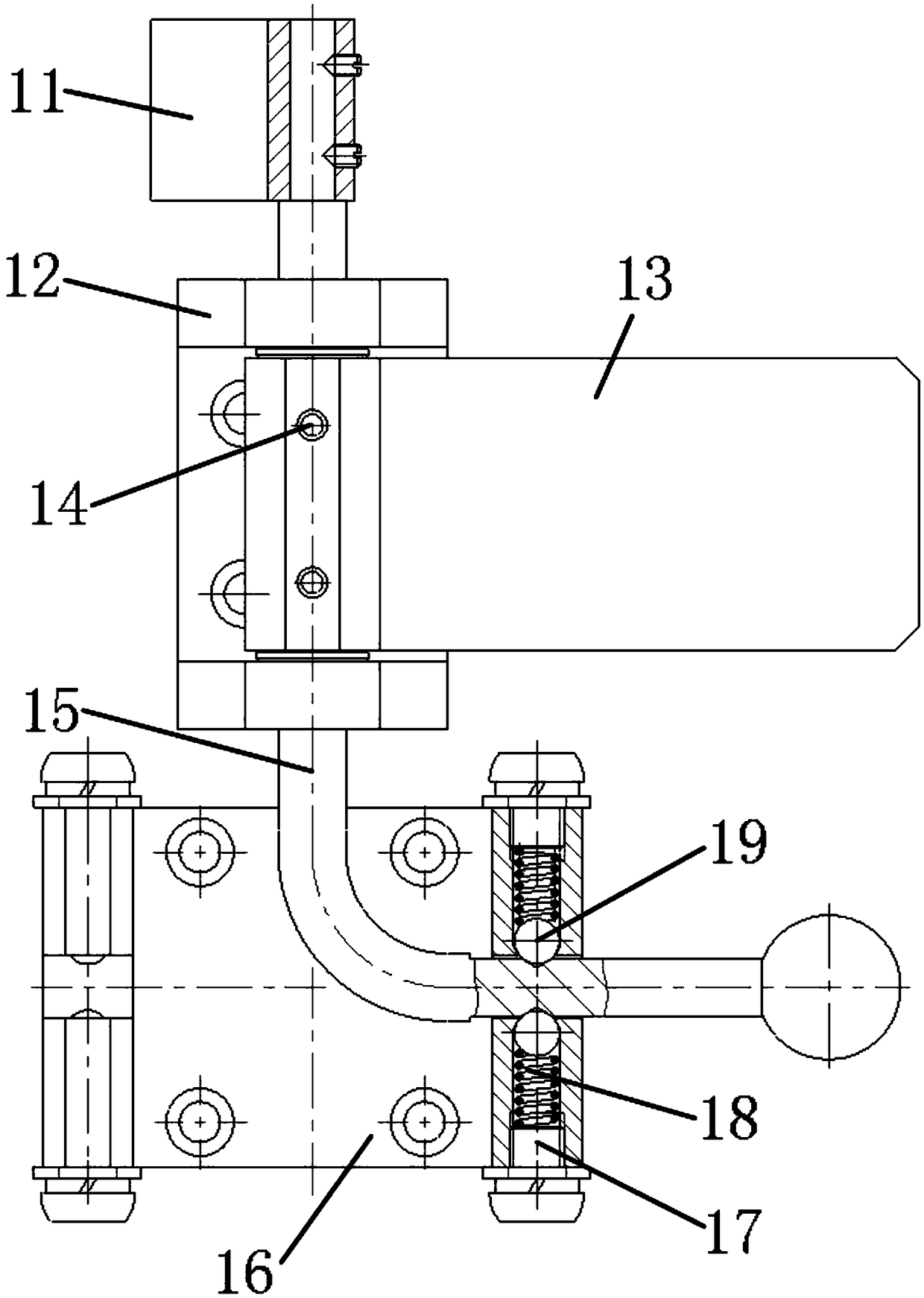
[0051] Example 3, such as figure 2 and image 3 Shown:

[0052] The difference between this embodiment and embodiment 2 is that each group of rotation stop mechanism 1 also includes:

[0053] Mounting plate 11; the mounting plate 11 is fixedly connected to the first end of the rotating shaft 15, and the measuring head of the proximity displacement sensor is installed on the mounting plate 11;

[0054] Sensor seat 110; the sensor seat 110 is fixedly installed on the yaw frame 3, the body of the proximity displacement sensor is installed on the sensor seat 110, and the body of the proximity displacement sensor matches the probe position of the proximity displacement sensor; when the dead bolt When 13 is stuck in the buckle 111, the body of the proximity displacement sensor approaches the probe of the proximity displacement sensor, and the probe of the proximity displacement sensor detects the signal of the body of the proximity displacement sensor; When 111 was disengaged, t...


PUM


Abstract

The invention discloses a rolling freedom revolution stop mechanism for a helicopter dynamic flight simulator. A rolling frame and a yaw frame are locked through clamping of a lock tongue into a lockbuckle while a device is stationary, the roll frame is prevented from rotating relative to the yaw frame, the shortcoming of insufficient motor braking torque is overcome, and safety of a pilot is ensured; when the revolution stop mechanism is stopped, the body of a proximity displacement sensor is close to a probe of the proximity displacement sensor, a signal of the body of the proximity displacement sensor is detected by the probe of the proximity displacement sensor, the signal is transmitted to a safety control system, a driving motor is not allowed to work at this time, and secure interlocking is achieved; when the revolution stop mechanism is unlocked, the body of the proximity displacement sensor is separated from the probe of the proximity displacement sensor, the signal of the body of the proximity displacement sensor can not be detected by the probe of the proximity displacement sensor, the driving motor is allowed to work at this time, and safe operation is ensured.

Description

technical field [0001] The invention belongs to the technical field of helicopter dynamic flight simulation, and in particular relates to a rotation stop mechanism for a rolling degree of freedom used in a helicopter dynamic flight simulator. Background technique [0002] Helicopter dynamic flight simulator is a kind of simulation training equipment based on centrifuge platform. It can realize the attitude change of any three degrees of freedom of the pilot in space under continuous load, and it is easy to induce a variety of spatial orientation disorders. It can simulate a variety of abnormal flight states in the ground environment, and has achieved the ability for the pilot to recognize the orientation disorder and grasp the environment in which the orientation disorder occurs. , forms of expression and ways to overcome them. [0003] The three degrees of freedom in space are yaw, roll and pitch degrees of freedom. The yaw degree of freedom is realized by the motor-driven...

Claims


Application Information

Patent Timeline
Patent Type & Authority Applications(China)
IPC IPC(8): G09B9/08G09B9/12
CPCG09B9/085G09B9/12Y02T90/00
Inventor 何阳蒋春梅宋琼黎启胜尹娇妹张建全罗龙胡荣华白俊林
Owner GENERAL ENG RES INST CHINA ACAD OF ENG PHYSICS
Why Eureka
Try Eureka