Four-degree-of-freedom helicopter dynamic flight simulator

A dynamic flight and helicopter technology, applied in the simulation devices, simulators, instruments and other directions of space navigation conditions, can solve the problems of reduced motor stability, large cockpit vibration, and the device cannot provide yaw motion, etc., to reduce vibration, reduce Effect of Moment of Inertia

Pending Publication Date: 2018-12-07
GENERAL ENG RES INST CHINA ACAD OF ENG PHYSICS
View PDF9 Cites 4 Cited by
  • Summary
  • Abstract
  • Description
  • Claims
  • Application Information

AI Technical Summary

Problems solved by technology

[0003] Regarding the structure of the simulator, the rotating arm of the centrifugal simulator is currently connected to the main motor, and the rotating arm is directly installed on the shaft of the main motor. Since the main motor is connected in series with the rotating arm, the vibration of the main motor is directly transmitted to the rotating arm and the cockpit structure, causing the cockpit The vibration is too large, and the unbalanced load formed by the rotating arm and the cockpit reacts on the main motor shaft, reducing the stability of the motor
[0004] In terms of simulator functions, the currently disclosed flight simulators are three-freedom simulators, which can provide rolling and pitching motions for test pieces or trainers in a centrifugal field environment, but such devices cannot provide yaw motions; Provides a simulation device for rolling, pitching and yaw motion for test pieces or training personnel. This device cannot provide the freedom to realize centrifugal motion, and can only move in a non-centrifugal field

Method used


Image

  • Four-degree-of-freedom helicopter dynamic flight simulator
  • Four-degree-of-freedom helicopter dynamic flight simulator
  • Four-degree-of-freedom helicopter dynamic flight simulator

Examples


Embodiment 1

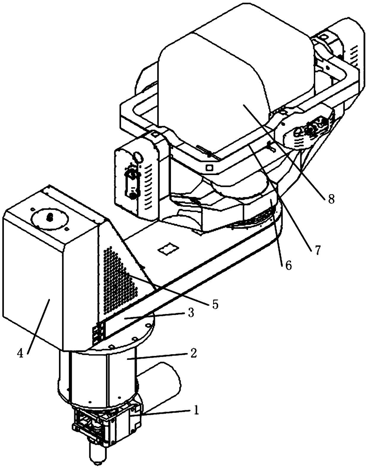
[0044] Example 1, such as figure 1 , figure 2 and image 3 Shown:

[0045] Four degrees of freedom helicopter dynamic flight simulator, including:

[0046] A cockpit 8 for carrying people; the cockpit 8 is used as a part for carrying pilots;

[0047] A pitch drive system for pitching the cockpit 8;

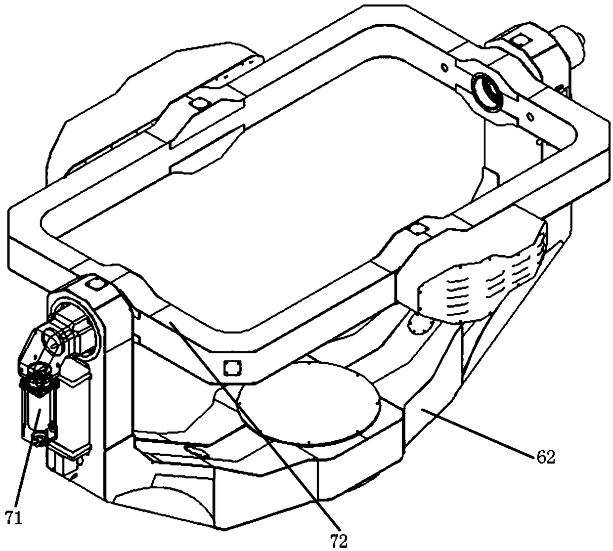
[0048] The rolling unit 7 used for the rolling action of the cockpit 8; the rolling unit 7 includes a rolling drive system 71 and a rolling frame 72, and the cockpit 8 performs a pitching motion in the rolling frame 72 after being connected by a pitching drive system;

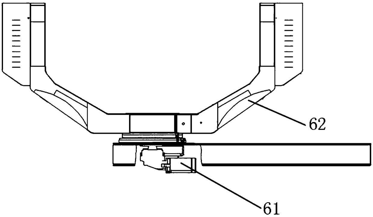
[0049] The yaw unit 6 used for the cockpit 8 to perform yaw action; the yaw unit 6 includes a yaw drive system 61 and a yaw frame 62, and the roll unit 7 performs yaw in the yaw frame 62 after being connected through the yaw drive system 61 sailing;

[0050] The centrifugal unit used to provide centrifugal force for the cabin 8 and make the cabin 8 perform centrifugal action; the yaw unit 6 is connected to t...

Embodiment 2

[0053] Example 2, such as figure 1 Shown:

[0054] The difference between this embodiment and Embodiment 1 is that the centrifugal unit includes:

[0055] Main deceleration motor 1;

[0056] transmission unit 2;

[0057] The rotating arm 3; the power output end of the main reduction motor 1 is connected to the power input end of the transmission unit 2, and the power output end of the transmission unit 2 is fixedly connected to the first end of the rotating arm 3;

[0058] counterweight unit 4;

[0059] The instrument cabin 5 ; the counterweight unit 4 and the instrument cabin 5 are all installed on the upper part of the first end of the rotating arm 3 , and the yaw frame 62 is installed on the upper part of the second end of the rotating arm 3 .

[0060] Among them, the main reduction motor 1 drives the rotating arm 3 to rotate through the transmission unit 2, and the centrifugal motion is transmitted to the rotating arm 3 and the installation parts of the rotating arm 3;...

Embodiment 3

[0061] Example 3, such as figure 1 and Figure 4 Shown:

[0062] The difference between this embodiment and Embodiment 2 is that the transmission unit 2 includes:

[0063] The main shaft 21; the output shaft of the main deceleration motor 1 is connected to one end of the main shaft 21 to transmit torque;

[0064] Bearing system 23;

[0065] Machine base 22; The machine base 22 is fixed on the ground, the two ends sidewalls of the main shaft 21 are connected with the rotating part of the bearing system 23, and the non-rotating part of the bearing system 23 is fixed on the machine base 22; The other end of the main shaft 21 is connected with the rotating arm The first end of 3 is fixedly connected.

[0066] The adoption of the transmission unit 2 prevents the vibration of the main reduction motor 1 from being directly transmitted to the rotating arm 3, resulting in excessive vibration of the entire dynamic flight simulator, and the unbalanced force of the rotating arm 3 and ...


PUM


Abstract

The invention discloses a four-degree-of-freedom helicopter dynamic flight simulator. Simultaneous simulation of three modes of space yaw, rolling and pitching can be achieved under the centrifugal field, and overload simulation is achieved; mounting components on a rotating arm are arranged in a centralized manner, a balancing design method is adopted, a counterweight unit is designed according to the trimming principle and mounted on the rotating arm, the mass center of the dynamic flight simulator is placed on the revolution axis, and vibration of the simulator caused by imbalance is reduced. The asymmetric rotating arm structure is adopted to reduce the rotational inertia of the dynamic flight simulator, and energy consumption of the dynamic flight simulator is reduced; a transmissionunit is adopted to prevent vibration of a main reduction motor from being directly transmitted to the rotating arm to make the entire dynamic flight simulator vibrate excessively, the unbalanced forceof the rotating arm and the rotating arm mounting components is transmitted to the civil part through the transmission unit, and running stability of the main reduction motor is enhanced.

Description

technical field [0001] The invention belongs to the technical field of helicopter dynamic flight simulation, in particular to a four-degree-of-freedom helicopter dynamic flight simulator. Background technique [0002] The four-degree-of-freedom helicopter dynamic flight simulator is a simulated motion platform based on a centrifuge. It simulates the change of the pilot's spatial attitude through the synthesis of different degrees of freedom, simulates the abnormal flight attitude of the helicopter in the ground environment, and realizes the spatial orientation of the pilot. Excellent visual, vestibular and proprioceptive sensations enable pilots to have good spatial orientation. [0003] Regarding the structure of the simulator, the rotating arm of the centrifugal simulator is currently connected to the main motor, and the rotating arm is directly installed on the shaft of the main motor. Since the main motor is connected in series with the rotating arm, the vibration of the...

Claims


Application Information

Patent Timeline
IPC IPC(8): G09B9/12G09B9/10
CPCG09B9/10G09B9/12
Inventor 蒋春梅何阳宋琼黎启胜尹娇妹胡荣华陈磊赵世鹏白俊林尹鹏
Owner GENERAL ENG RES INST CHINA ACAD OF ENG PHYSICS
Why Eureka
Try Eureka