Supercharge Your Innovation With Domain-Expert AI Agents!

Wafer processing method

A processing method and wafer technology, applied to metal processing equipment, manufacturing tools, and machine tools suitable for grinding the edge of workpieces, etc., can solve the problems of immersion in solution or high-temperature heating, etc., to suppress the influence of unevenness and simple processing Effect

Pending Publication Date: 2018-12-07
DISCO CORP
View PDF4 Cites 0 Cited by
  • Summary
  • Abstract
  • Description
  • Claims
  • Application Information

AI Technical Summary

Problems solved by technology

However, since the substrate is bonded to the wafer with an adhesive such as thermoplastic wax, cumbersome operations such as dipping the substrate in a solution or heating at a high temperature are required when peeling the substrate from the ground wafer.

Method used


Image

  • Wafer processing method
  • Wafer processing method
  • Wafer processing method

Examples


Embodiment Construction

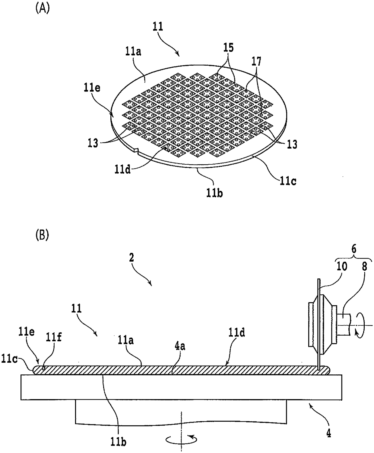
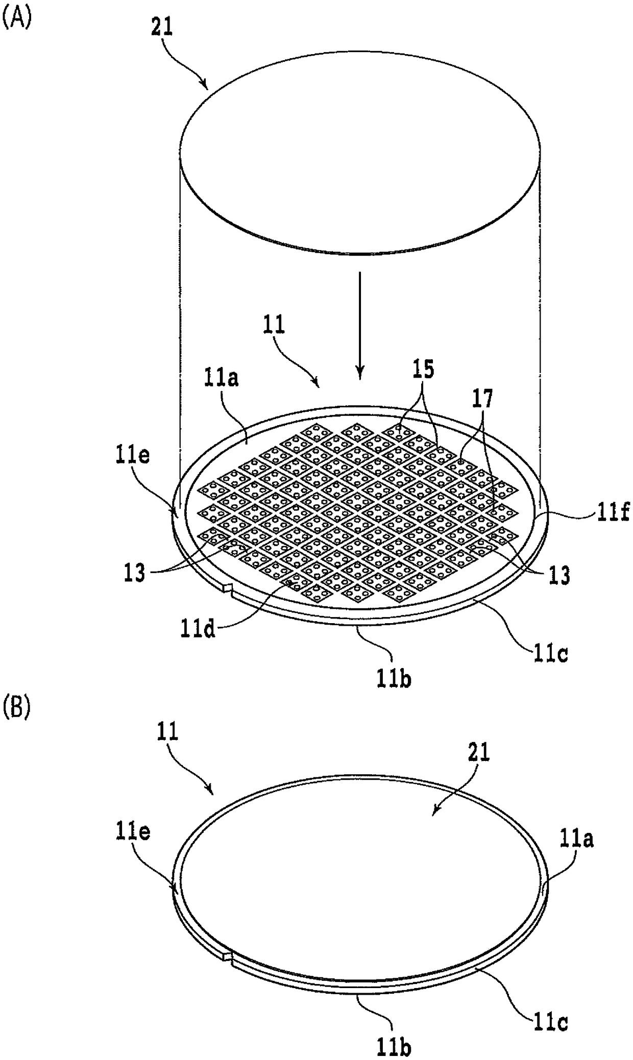
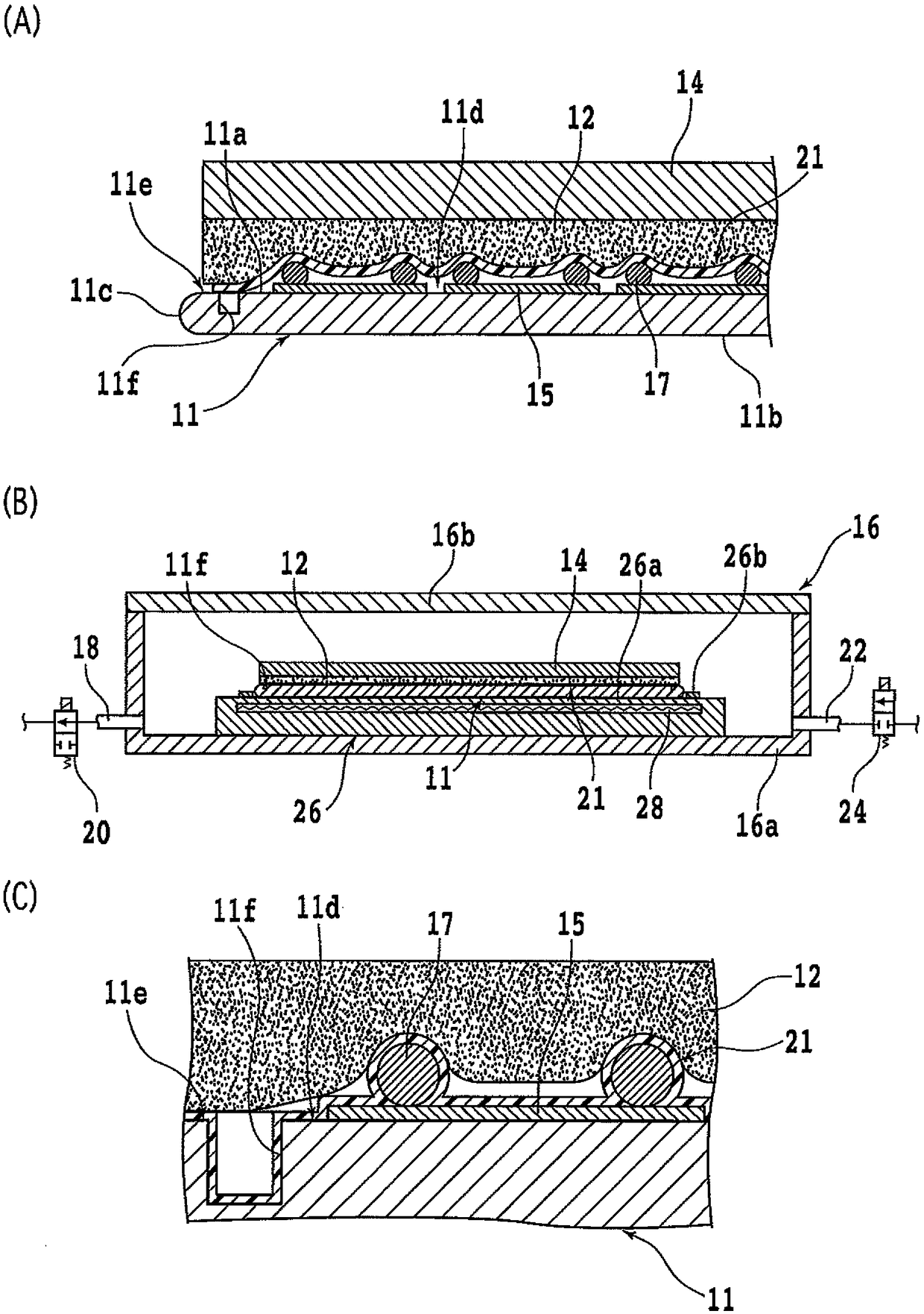
[0035] An embodiment of one embodiment of the present invention will be described with reference to the drawings. The wafer processing method of the present embodiment includes an annular groove forming step (refer to figure 1 (B)), the step of sticking the protective film (refer to figure 2 of (A), figure 2 of (B), image 3 of (A), image 3 of (B), image 3 (C)), wafer formation step with protection member (refer to Figure 4 of (A), Figure 4 of (B), Figure 4 (C)), grinding steps (refer to Figure 5 of (A), Figure 5 (B)) and the stripping step (see Image 6 ).

[0036] In the annular groove forming step, an annular groove having a depth exceeding the finished thickness of the wafer is formed on the front side of the wafer along the remaining area of ​​the periphery of the device region provided around the front side of the wafer. In the step of attaching the protective film, a protective film having no adhesive force due to an adhesive (paste) is adhered to th...


PUM


Abstract

The invention provides a wafer processing method, being able to inhibit the concavo-convex influence on the front side while grinding the back side of a wafer, and being simple in processing after grinding. The wafer processing method includes an annular groove forming step, a close contact making step, a step of forming a wafer with a protective member, a grinding step, and a peeling step. The wafer has a device area and a peripheral marginal area surrounding the device area on the front side, and devices each having asperities are formed in the device area. In the annular groove forming step, an annular groove is formed on the front side of the wafer along the inner circumference of the peripheral marginal area, and the depth of the annular groove exceeds the finishing thickness of the wafer. I n the close contact making step, the device area and the annular groove are covered with a protective film, and the protective film is bring into close contact with the front side of the wafer. In the step of forming a wafer with a protective member, a wafer with a protective member is formed by covering the protective film and the exposed peripheral marginal area are covered with the protective member formed by hardened liquid resin. In the grinding step, the back side of the wafer is grinded to thin the wafer to the finishing thickness while the protective member side is retained. Inthe peeling step, the protective member and the protective film are peeled off from the device area.

Description

technical field [0001] The present invention relates to a wafer processing method which is used when grinding a wafer having concavities and convexities on the front surface. Background technique [0002] In order to reduce the size and weight of device chips incorporated into various electronic devices, etc., chances of thinning wafers before being divided into device chips increase. For example, the wafer can be ground and thinned by holding the front side of the wafer on which the device is installed by a chuck table and pressing a rotating grinder tool to the back side of the wafer. [0003] When grinding a wafer by the above-mentioned method, a protective member is usually attached to the front side of the wafer (for example, refer to Patent Document 1). Thereby, it is possible to prevent the device on the front side from being damaged due to force applied during grinding or the like. As the protective member, for example, an adhesive tape formed of a material such as...

Claims


Application Information

Patent Timeline
Patent Type & Authority Applications(China)
IPC IPC(8): H01L21/304H01L29/06
CPCH01L21/304H01L29/06H01L2221/68327H01L2221/6834H01L21/78B24B9/065H01L21/6836H01L21/76H01L21/67132H01L21/3043
Inventor 关家一马
Owner DISCO CORP
Features
  • R&D
  • Intellectual Property
  • Life Sciences
  • Materials
  • Tech Scout
  • Unparalleled Data Quality
  • Higher Quality Content
  • 60% Fewer Hallucinations
Learn More