Manufacturing method of terahertz corrugated feed source horn

A feed horn and manufacturing method technology, which is applied in the field of precision and ultra-precision device processing, can solve the problems of low processing accuracy of corrugated microstructures, high difficulty of gold plating, and difficult processing of corrugated microstructures, etc., and achieve high-level high-precision lamination Assembling, solving technical problems, and ensuring the effect of precise manufacturing

Inactive Publication Date: 2018-12-07
SHANGHAI SPACEFLIGHT ELECTRONICS & COMM EQUIP RES INST +1
View PDF11 Cites 6 Cited by
  • Summary
  • Abstract
  • Description
  • Claims
  • Application Information

AI Technical Summary

Problems solved by technology

[0006] The purpose of the present invention is to provide a method for manufacturing a terahertz corrugated feed horn, so as to solve the problem of difficult processing of corrugated microstructures in the high-frequency corrugated feed horn produced by traditional techniques
[0007] The second purpose of the present invention is to provide a method for manufacturing a terahertz corrugated feed horn, so as to solve the problem of low processing precision of corrugated fine structures in the high-frequency corrugated feed horn produced by traditional technology
[0008] The third purpose of the present invention is to provide a method for manufacturing a terahertz corrugated feed horn, so as to solve the problem that it is difficult to plate gold on the inner surface of the high-frequency corrugated feed horn in the traditional technology

Method used


Image

  • Manufacturing method of terahertz corrugated feed source horn
  • Manufacturing method of terahertz corrugated feed source horn
  • Manufacturing method of terahertz corrugated feed source horn

Examples


Embodiment Construction

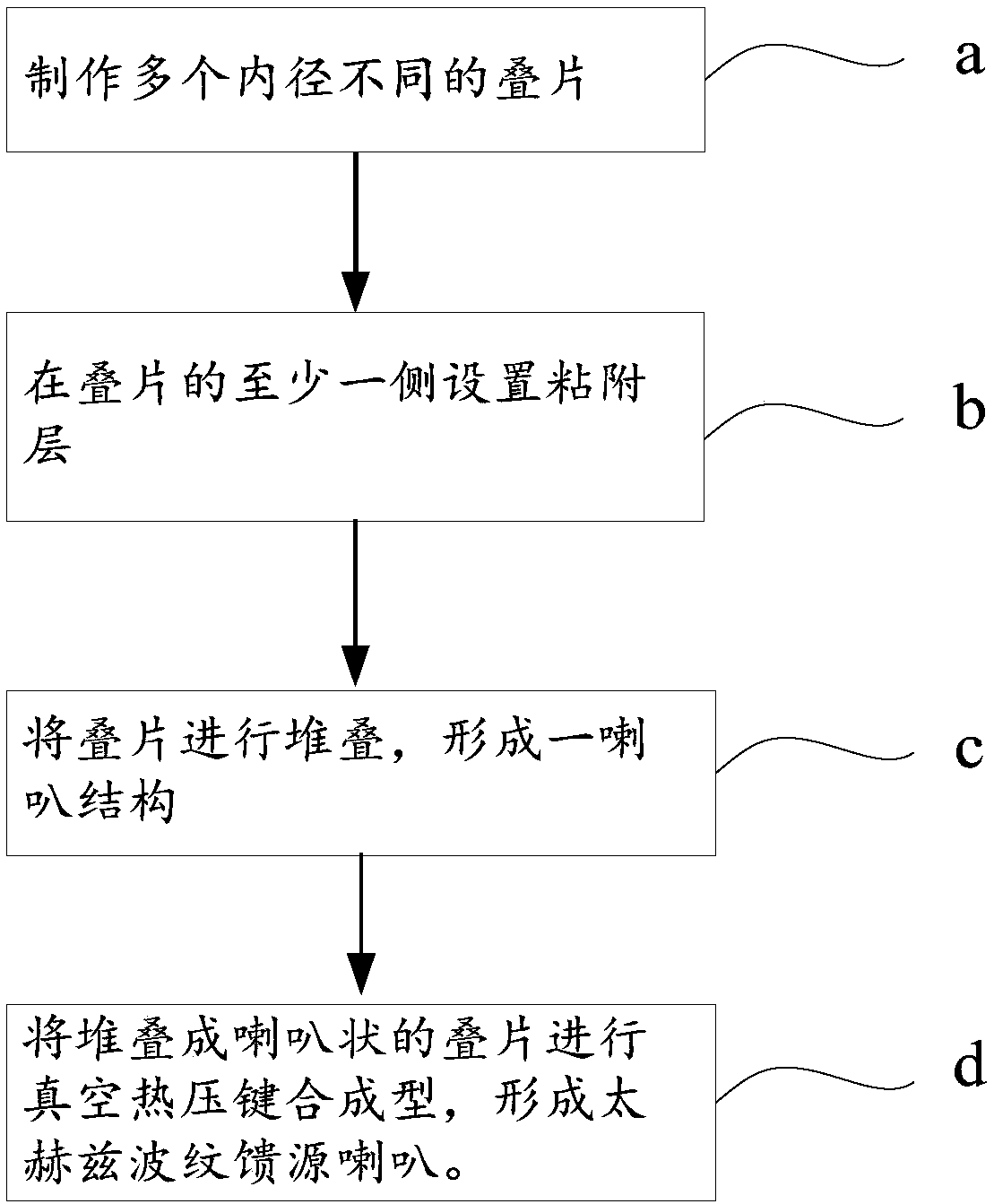
[0046] The present invention will be described in detail below in conjunction with specific embodiments. The following examples will help those skilled in the art to further understand the present invention, but do not limit the present invention in any form. It should be noted that those skilled in the art can make several changes and improvements without departing from the concept of the present invention. These all belong to the protection scope of the present invention.

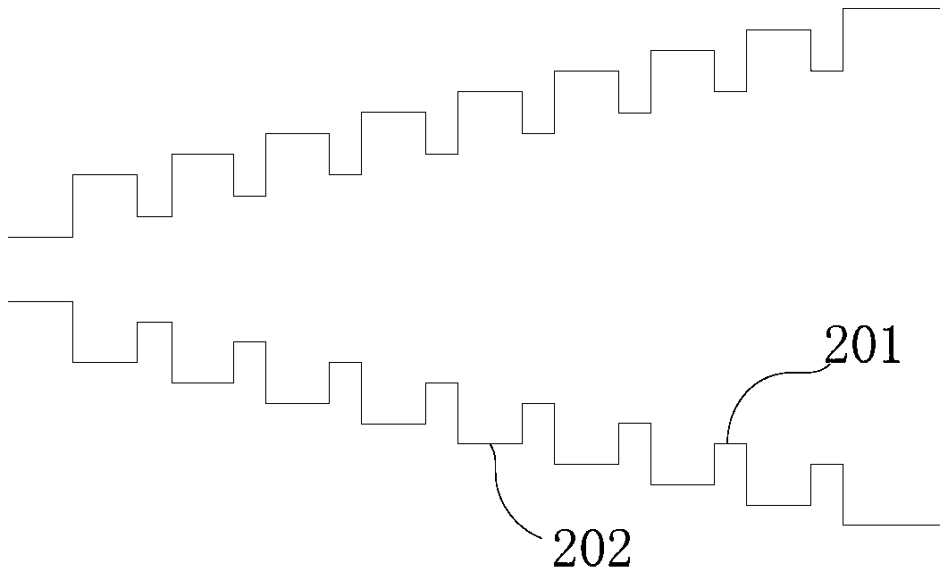
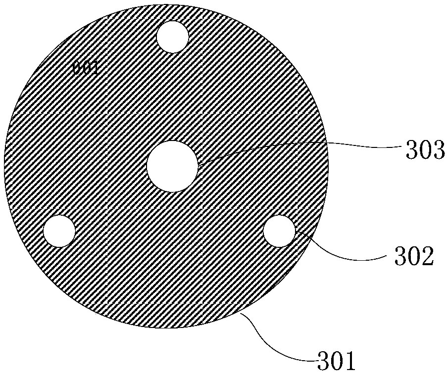
[0047] The cavity structure of the feed horn to be produced in this embodiment is as follows: figure 2 As shown, the inner cavity is an alveolar structure, the width of the tooth 201 is 0.025mm, the width of the groove 202 is 0.014mm, the input diameter D_in0.236mm, the input diameter D_in0.954mm, and the number of teeth are 60. The structure is divided into laminations, and the schematic diagram of the lamination structure is as follows image 3As shown, the laminations 301 include tooth laminations ...


PUM


Abstract

The invention discloses a manufacturing method of a terahertz corrugated feed source horn, which converts a three-dimensional annular inner cavity tooth-slot microstructure difficult to be processed into a two-dimensional planar lamination structure easy to be electroformed, wherein the lamination width is the inner cavity tooth width or slot width. The manufacturing method specifically comprisesthe steps of fabricating laminations required by the feed source horn in advance; setting an adhesive layer on at least one side of each lamination; then stacking the laminations, wherein the lamination with the smallest inner diameter is placed at the bottom layer of an assembly base when the laminations are stacked, and the stacked laminations are of a horn-shaped structure; and performing vacuum thermocompression bonding on the laminations stacked into the shape of a horn to form the terahertz corrugated feed source horn. The manufacturing method solves a problem that it is difficult to process an inner corrugated microstructure of the high-frequency corrugated feed source horn according to the traditional technology.

Description

technical field [0001] The invention relates to the technical field of precision and ultra-precision device processing, in particular to a method for manufacturing a terahertz corrugated feed horn based on LIGA-precision assembly technology. Background technique [0002] Terahertz (THz) refers to electromagnetic waves with a frequency between 0.1THz and 10THz. It belongs to the far-infrared band and has technical advantages such as large bandwidth, high resolution and strong penetration. The satellite is equipped with a high-performance THz detector to achieve precise detection of elements such as the atmosphere, ocean and space environment. In the antenna feed system of the detector, the feed horn is a high-gain concentrated antenna radiator located in the antenna feed system. Between the surface antenna and the receiver, it is a key component of the detection system, and its structural form, structural parameters and processing accuracy directly affect the performance of t...

Claims


Application Information

Patent Timeline
Patent Type & Authority Applications(China)
IPC IPC(8): H01Q13/02
CPCH01Q13/0291
Inventor 符容周义丁蕾罗燕王立春朱增伟刘亚鹏李安心赵涌
Owner SHANGHAI SPACEFLIGHT ELECTRONICS & COMM EQUIP RES INST
Why Eureka
Try Eureka