
Implementation of high efficiency battery charger for electronic devices

A technology of battery packs and power converters, applied in the direction of circuit devices, battery circuit devices, current collectors, etc.

Pending Publication Date: 2018-12-07
NXP BV
View PDF5 Cites 1 Cited by
  • Summary
  • Abstract
  • Description
  • Claims
  • Application Information

AI Technical Summary

Problems solved by technology

Charging current has traditionally been limited to about 3 amps due to limitations in cables, connectors, and the charge acceptance rate of lithium-ion (Li-ion) batteries in mobile devices

Method used


Image

  • Implementation of high efficiency battery charger for electronic devices
  • Implementation of high efficiency battery charger for electronic devices
  • Implementation of high efficiency battery charger for electronic devices

Examples


Embodiment Construction

[0023] It should be understood that the drawings are only schematic and not drawn to scale. It should also be understood that the same reference numbers are used throughout the drawings to indicate the same or similar parts.

[0024] The description and drawings illustrate the principles of the various exemplary embodiments. It will be appreciated that those skilled in the art will be able to devise various arrangements that, although not explicitly described or shown herein, embody the principles of the invention and are included within its spirit and scope. In addition, all the examples cited in this article are mainly intended for teaching purposes to assist the reader to understand the principles of the present invention and the concepts provided by the inventors to deepen the field, and all examples should be considered as not limiting such specific Quote examples and conditions. Additionally, as used herein, the term "or" means a non-exclusive or (ie, and / or) unless ot...


PUM


Abstract

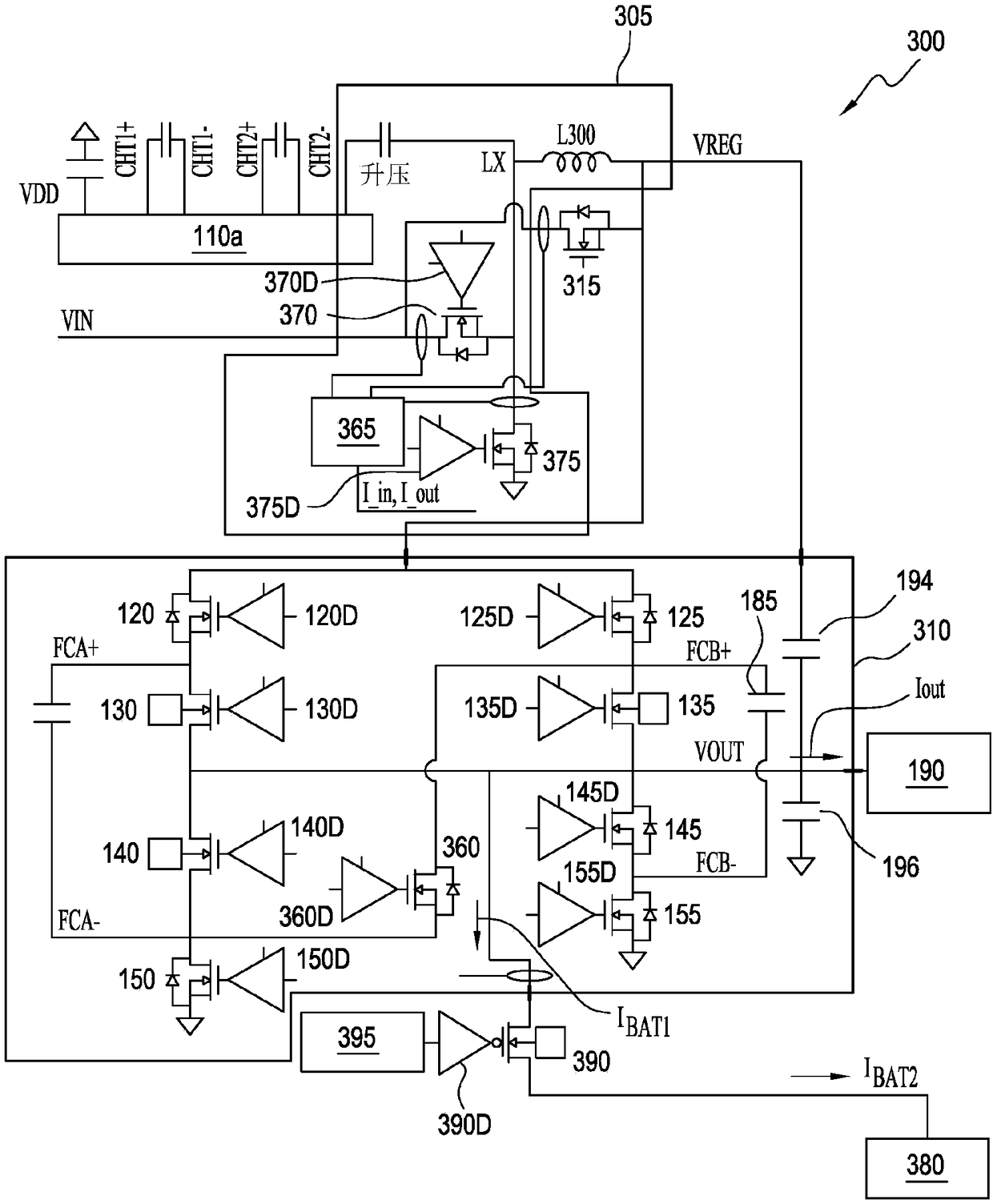
A power converter includes a power conditioning circuit to receive input power and set operating voltages of the power converter, a current sensing circuit to determine an input current of the power converter, a voltage regulation circuit to step down a voltage level of the input power, a charge pump circuit to store charge delivered by the voltage regulation circuit and output to a load a currentlarger than the input current, and a power path controller to control switching and provide feedback within the power converter.

Description

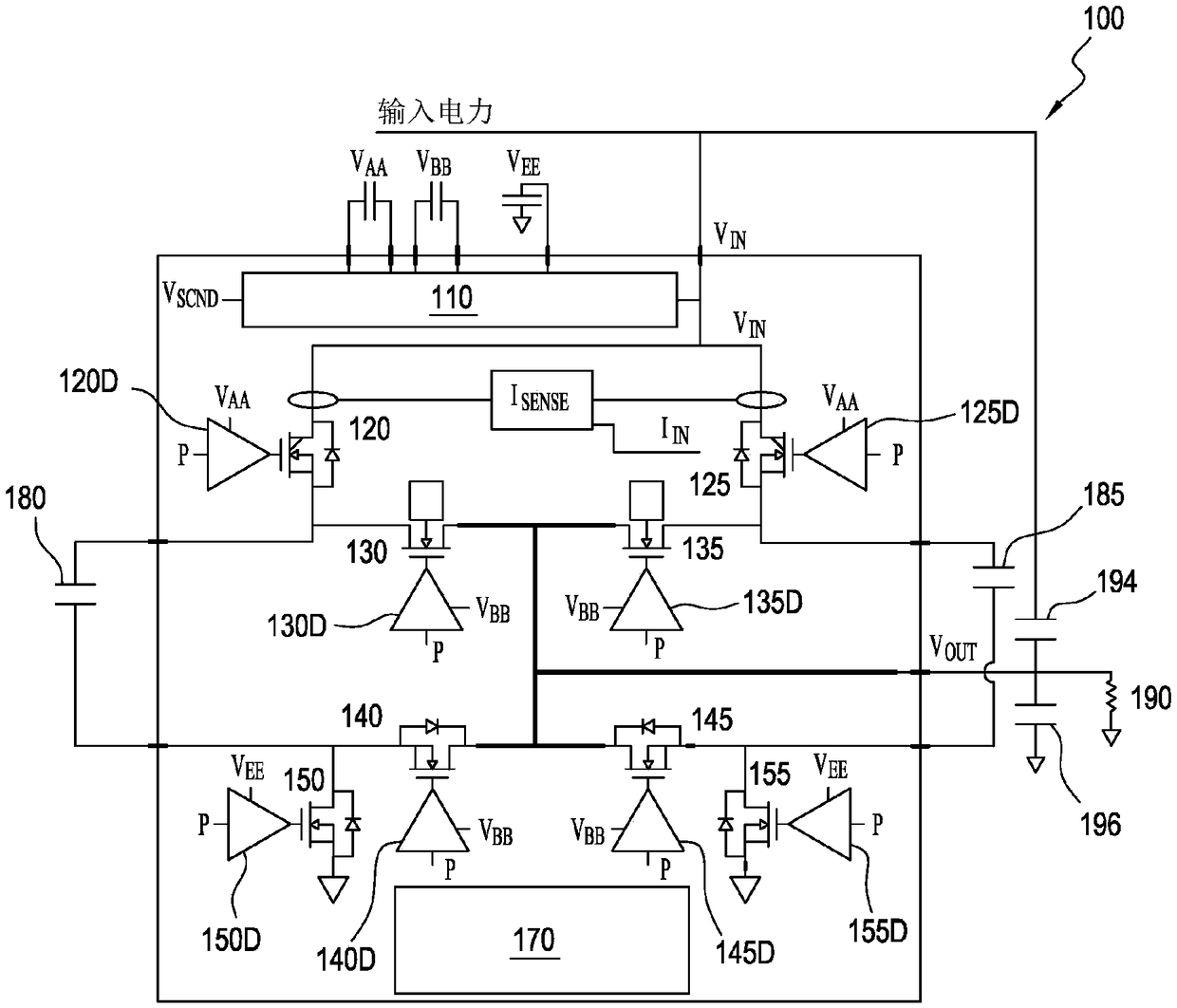
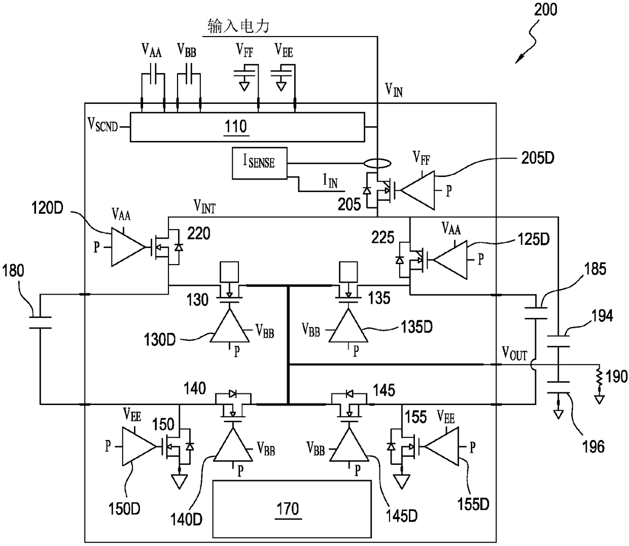
[0001] Cross References to Related Applications [0002] This application is a continuation-in-part of Serial No. 15 / 600,244 filed May 19, 2017, which is incorporated by reference for all purposes as if fully set forth herein. technical field [0003] Various embodiments disclosed herein relate to charging mobile and other electronic devices, including implementation options for high-efficiency 2:1, 3:1, and 3:2 switched capacitor converters designed for high-voltage DC battery charging. Alternatively, the device may provide a bypass mode setting for a DC 1:1 power path from Vin to Vout. Two 8-FET and 9-FET topological approaches are described along with applicable control circuits. An additional 9-FET topology is described where a buck regulator is placed in parallel to the ninth FET to provide efficient power transfer when the Vin to Vout ratio is higher than the available switched capacitor converter ratio. Background technique [0004] Fast battery charging of smartpho...

Claims


Application Information

Patent Timeline
Patent Type & Authority Applications(China)
IPC IPC(8): H02M3/158H02M3/07H02J7/00
CPCH02M3/07H02M3/158H02J2207/20H02J7/0068H02J7/00712H02M3/072H02M3/077H02M1/007H02J7/00
Inventor 罗伯特·克兰II·科斯比彼得·克里斯蒂亚安斯
Owner NXP BV
Learn More