Waste gas treatment device for paint production

A waste gas treatment device and paint technology, applied in mixers with rotating stirring devices, transportation and packaging, chemical/physical processes, etc., can solve the problems of low quality of waste gas treatment, high labor intensity of operators, and low efficiency of paint waste gas treatment To achieve the effect of enhancing the quality of waste gas treatment, improving stability and reducing waste

Inactive Publication Date: 2018-12-11
WUHU SANSHAN LONGCHENG NEW MATERIALS
View PDF5 Cites 0 Cited by
  • Summary
  • Abstract
  • Description
  • Claims
  • Application Information

AI Technical Summary

Problems solved by technology

[0003] The purpose of the present invention is to overcome the problems of low paint waste gas treatment efficiency, low waste gas treatment quality, and high labor intensity of operators existing in the existing paint waste gas treatment device, and to provide a device with reasonable structure design, high work efficiency, and good waste gas treatment quality. Exhaust gas treatment device suitable for paint production with low labor intensity for operators

Method used


Image

  • Waste gas treatment device for paint production
  • Waste gas treatment device for paint production
  • Waste gas treatment device for paint production

Examples


Embodiment 1

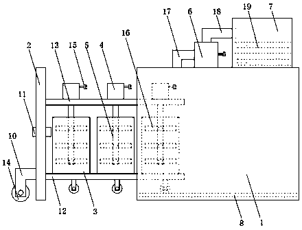
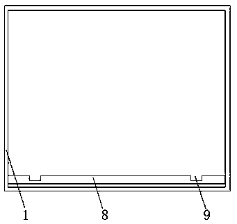
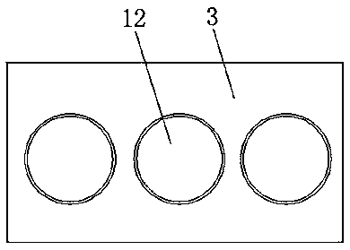
[0018] as attached Figure 1-3 As shown, a waste gas treatment device suitable for paint production includes a sealed chamber 1, a sealed door 2, a paint bucket 3, a motor 4, a transmission shaft 5, an air suction pump 6 and a treatment chamber 7, and is characterized in that: A positioning plate 8 is arranged in the sealed chamber 1, and a positioning groove 9 is arranged on the positioning plate 8. The two sides of the sealed door 2 are respectively provided with a connecting plate 10, a bottom plate 12, and a top plate 13. The paint bucket 3 is provided with On base plate 12, described motor 4 is arranged on the top plate 13, and is provided with power line 15 on motor 4, and described power transmission shaft 5 one end is connected with motor 4, and the other end is arranged in paint bucket 3, and in The transmission shaft 5 in the paint bucket 3 is provided with a stirring rod 16, and the motor 4 drives the transmission shaft 5 to rotate, and the transmission shaft 5 driv...

Embodiment 2

[0024] as attached Figure 4 Shown: a waste gas treatment device suitable for paint production, including a sealed chamber 1, a sealed door 2, a paint bucket 3, a motor 4, a drive shaft 5, an air suction pump 6 and a treatment chamber 7, characterized in that: A positioning plate 8 is arranged in the sealed chamber 1, and a positioning groove 9 is arranged on the positioning plate 8. The two sides of the sealed door 2 are respectively provided with a connecting plate 10, a bottom plate 12, and a top plate 13. The paint bucket 3 is provided with On base plate 12, described motor 4 is arranged on the top plate 13, and is provided with power line 15 on motor 4, and described power transmission shaft 5 one end is connected with motor 4, and the other end is arranged in paint bucket 3, and in The transmission shaft 5 in the paint bucket 3 is provided with a stirring rod 16, and the motor 4 drives the transmission shaft 5 to rotate, and the transmission shaft 5 drives the stirring r...


PUM


Abstract

The invention discloses a waste gas treatment device for paint production. The waste gas treatment device comprises a sealing chamber, a sealing door, a paint bucket, a motor, a drive shaft, an air suction pump and a treatment chamber, and is characterized in that a positioning plate is arranged in the sealing chamber; a connecting plate, a bottom plate and a top plate are respectively arranged atboth sides of the sealing door; the paint bucket is arranged on the bottom plate; the motor is arranged on the top plate; one end of the drive shaft is connected with the motor; the air suction pumpis arranged at the top part of the sealing chamber; a power source line, a connecting pipe and an air conveying pipe are arranged on the air suction pump; the treatment chamber is arranged at the toppart of the sealing chamber; a waste gas absorbing liquid is arranged in the treatment chamber. The waste gas treatment device has the advantages that by arranging an air ventilating valve on the sealing door, the gas flow can be blown into the sealing chamber after treatment of waste gas via the air ventilating valve, the air pressure in the sealing chamber is increased, and the sealing door canconveniently pull the bottom plate and the top plate out of the sealing chamber; the treatment efficiency of paint waste gas is improved, and the pulling intensity of an operator is decreased.

Description

technical field [0001] The invention relates to the technical field of paint production, in particular to a waste gas treatment device suitable for paint production. Background technique [0002] A large amount of waste gas will be produced in the production of paint, containing a large amount of volatile organic compounds, mainly including benzene, toluene, xylene and methyl ethyl ketone, etc., which are extremely harmful to the human body, and even have the risk of carcinogenesis. The damage caused by the genetic material of the body may be accumulated through inheritance, and it will also affect future generations. Therefore, it is very important to remove the exhaust gas in the paint in the paint production process. Most of the paint is relatively viscous, and the exhaust gas contained in it is difficult to float out of the paint. On the surface, the traditional paint exhaust gas removal device uses stirring to remove the exhaust gas in the paint. Not only is the efficie...

Claims


Application Information

Patent Timeline
Patent Type & Authority Applications(China)
IPC IPC(8): B01D46/10B01D53/18B01F7/18B01F13/10B01F15/00
CPCB01D46/10B01D53/18B01F33/501B01F33/813B01F27/90B01F35/187B01F2101/30
Inventor 杨荣军张强
Owner WUHU SANSHAN LONGCHENG NEW MATERIALS
Why Eureka
Try Eureka