Pipeline cutting equipment on basis of inner side wall expansion clamping principles

A pipe cutting and principle technology, applied in the direction of metal processing equipment, clamping, large fixed members, etc., can solve the problems that the blade cannot completely penetrate the pipe at one time, the pipe section is uneven, and the cutting effect is poor

Inactive Publication Date: 2018-12-11
陈晨
View PDF6 Cites 8 Cited by
  • Summary
  • Abstract
  • Description
  • Claims
  • Application Information

AI Technical Summary

Problems solved by technology

[0003] In the prior art, the cutting of pipes is done by manual hand-held cutting machines, which is completely achievable for pipes with smaller diameters; but when the pipes to be cut have larger diameters, the cutting machine The blade cannot completely penetrate the en

Method used


Image

  • Pipeline cutting equipment on basis of inner side wall expansion clamping principles
  • Pipeline cutting equipment on basis of inner side wall expansion clamping principles
  • Pipeline cutting equipment on basis of inner side wall expansion clamping principles

Examples


Example Embodiment

[0034] The embodiments of the present invention will be described in detail below with reference to the accompanying drawings, but the present invention can be implemented in a variety of different ways defined and covered by the claims.
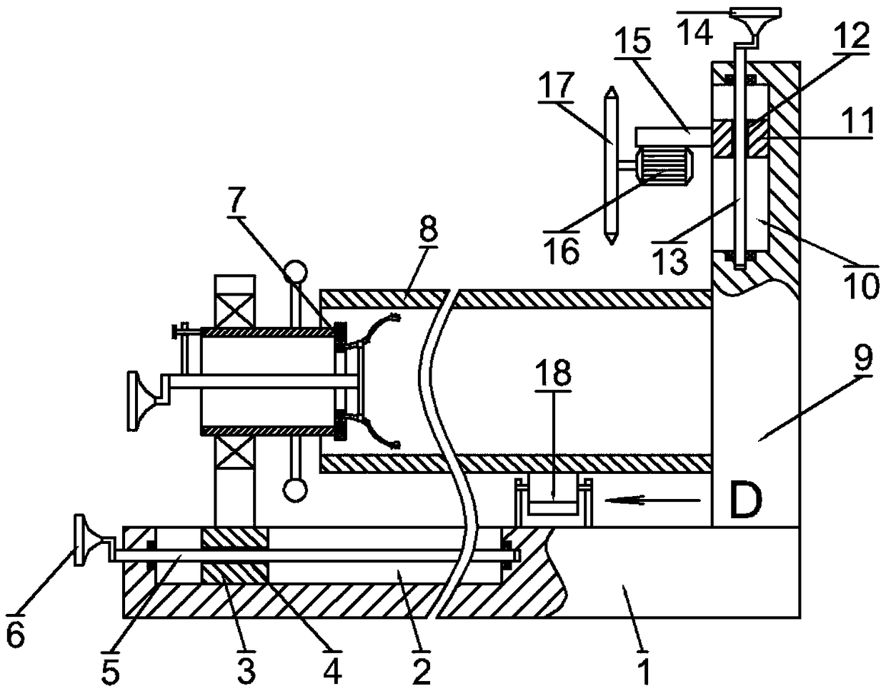
[0035] See figure 1 In this embodiment, a pipe cutting device based on the principle of inner wall expansion clamping includes a bottom plate 1. The bottom plate 1 is provided with a first moving groove 2 with an opening facing upward, and the first moving groove 2 is provided with The first moving block 3 is provided with a first threaded through hole 4, the first threaded through hole 4 is threaded with a first threaded rod 5, and both ends of the first threaded rod 5 are connected to the first moving groove 2 The two ends are rotatably connected, the left end of the first threaded rod 5 is fixedly connected with a first handle 6, the upper side of the first moving block 3 is fixedly connected with an expansion type clamping device 7, and the ...


PUM


Abstract

The invention provides pipeline cutting equipment on the basis of inner side wall expansion clamping principles. The pipeline cutting equipment comprises a bottom plate. A first movable groove with anupward opening is formed in the bottom plate, a first movable block is arranged in the first movable groove, a first threaded through hole is formed in the first movable block, a first threaded rod is connected into the first threaded through hole in a threaded manner, and two ends of the first threaded rod are rotationally connected with two ends of the first movable groove. The pipeline cuttingequipment has the advantages that a pipeline can be cut by a cutter head after rotating by a circle, the sections of the pipeline are flat, follow-up finishing can be omitted, and the cutting efficiency and cutting effects can be effectively improved; a rotary disc can be driven by a rotary sleeve to rotate, third threaded rods which are matched with the rotary disc can approach a support column,connecting sleeves can be driven by horizontal plates and first arc plates to rotate, second arc plates can be outwardly extended, accordingly, clamping protrusions on clamping plates can be squeezedwith the inner side walls of the pipeline in a contact manner, and the pipeline can be clamped.

Description

technical field [0001] The invention relates to the technical field of pipeline processing, in particular, to a pipeline cutting device based on the expansion clamping principle of the inner side wall. Background technique [0002] A pipeline is a device used to transport gas, liquid or fluid with solid particles connected by pipes, pipe connectors and valves. Usually, after the fluid is pressurized by blowers, compressors, pumps and boilers, it flows from the high-pressure part of the pipeline to the low-pressure part, and it can also be transported by the pressure or gravity of the fluid itself. Pipes are widely used, mainly in water supply, drainage, heat supply, gas supply, long-distance transportation of oil and natural gas, agricultural irrigation, hydraulic engineering and various industrial devices. [0003] In the prior art, the cutting of pipes is done by manual hand-held cutting machines, which is completely achievable for pipes with smaller diameters; but when t...

Claims


Application Information

Patent Timeline
IPC IPC(8): B23B31/40B23Q1/25B23Q3/06
CPCB23B31/40B23Q1/25B23Q3/06B23Q3/062B23Q3/064
Inventor 陈晨
Owner 陈晨
Why Eureka
Try Eureka