A precision gear processing machine tool

A technology for processing machine tools and gears, applied in metal processing machinery parts, gear cutting machines, metal processing equipment and other directions, can solve problems such as the inability to achieve multi-directional processing of gears, the quality of gear finished products, and the impact of processing accuracy, and achieve fast adjustment and reduction. Processing cost and the effect of improving processing efficiency

Active Publication Date: 2019-11-22
江苏爱雷德塑机有限公司
View PDF5 Cites 2 Cited by
  • Summary
  • Abstract
  • Description
  • Claims
  • Application Information

AI Technical Summary

Problems solved by technology

[0002] Gears refer to mechanical elements with gears on the rim that continuously mesh to transmit motion and power. Gears are the core transmission components in automobile movement. The quality of their processing will affect the vibration, noise and reliability of the automobile assembly and even the entire vehicle. When it is processed, it is usually fixed on the base of the machine tool with fixing parts. Most of the existing fixing parts are simple in structure and poor in stability. It will affect the quality of the finished gear, and many fixing parts only have the function of horizontal or vertical clamping, which cannot realize the multi-directional processing of gears. In addition, the height and width of most fixing parts are fixed. Unable to meet the needs of gears of different thickness and length, the scope of application is low, and the practicability is poor

Method used


Image

  • A precision gear processing machine tool
  • A precision gear processing machine tool
  • A precision gear processing machine tool

Examples


Embodiment Construction

[0022] The following will clearly and completely describe the technical solutions in the embodiments of the present invention with reference to the accompanying drawings in the embodiments of the present invention. Obviously, the described embodiments are only some, not all, embodiments of the present invention. Based on the embodiments of the present invention, all other embodiments obtained by persons of ordinary skill in the art without making creative efforts belong to the protection scope of the present invention.

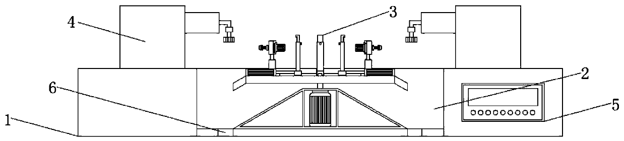
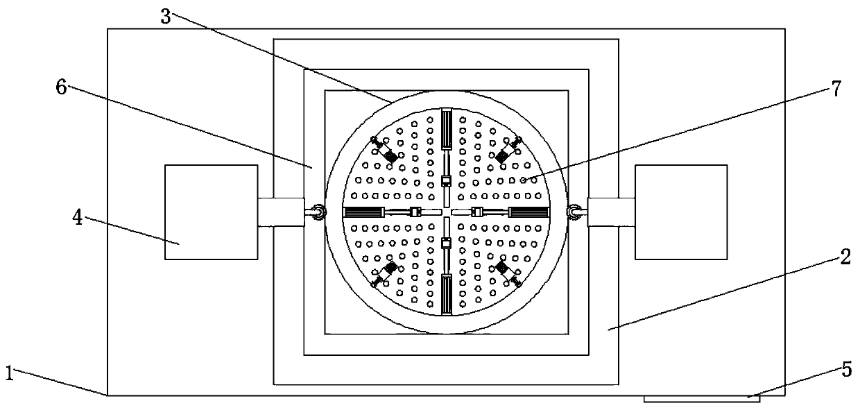
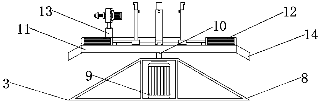
[0023] see Figure 1-5 , the present invention provides a technical solution: a precision gear processing machine tool, including a base 1, a groove 2, a fixing part 3, a processing tool 4, a control panel 5, a chip flute 6, a through hole 7, a protective cover 8, and a Y355 Motor 9, rotating shaft 10, turntable 11, first clamping part 12, second clamping part 13, hypotenuse 14, electric cylinder 15, slide rail 16, slider 17, fixing plate 18, fixing bolt 19, e...


PUM


Abstract

The invention discloses a precision gear machining machine tool base fixing part. A control panel is mounted on the right side of the front face of a base, the middle of the base is provided with a rove, a fixing part body is mounted in the middle of the groove, a Y355 motor is mounted in a protective cover which is mounted at the bottom end of the fixing part, and a rotating disc is mounted at the top of a rotating shaft which is fixedly connected to the top end of the Y355 motor. First clamping parts are mounted around the top of the rotating disc, an electric cylinder is mounted at one endof each first clamping part, a slider is mounted at one end of each electric cylinder, a fixing plate is mounted at the top of each slider, a retractable plate is fixedly connected to the top of eachfixing plate, a second clamping part is mounted on one side of each first clamping part, and machining tools are mounted on two sides of the top of the base. Top ends of the retractable plates are provided with flanging edges, grooves formed between the flanging edges and the fixing plates play a role in gear limiting and fixing to avoid gear sliding and shedding, and accordingly clamping effectsof the first clamping parts are improved, and gear machining precision is improved.

Description

technical field [0001] The invention relates to the technical field of gear processing devices, in particular to a precision gear processing machine tool. Background technique [0002] Gears refer to mechanical elements with gears on the rim that continuously mesh to transmit motion and power. Gears are the core transmission components in automobile movement. The quality of their processing will affect the vibration, noise and reliability of the automobile assembly and even the entire vehicle. When it is processed, it is usually fixed on the base of the machine tool with fixing parts. Most of the existing fixing parts are simple in structure and poor in stability. It will affect the quality of the finished gear, and many fixing parts only have the function of horizontal or vertical clamping, which cannot realize the multi-directional processing of gears. In addition, the height and width of most fixing parts are fixed. It cannot meet the needs of gears of different thicknes...

Claims


Application Information

Patent Timeline
Patent Type & Authority Patents(China)
IPC IPC(8): B23F23/00B23F23/06B23Q3/06
CPCB23F23/00B23F23/06B23Q3/06B23Q3/062
Inventor 艾蒙雁
Owner 江苏爱雷德塑机有限公司
Why Eureka
Try Eureka