Ship tail shaft bracket electric arc wire fusing 3D printing manufacturing method and product thereof

A technology of 3D printing and manufacturing methods, which is applied in the direction of manufacturing tools, arc welding equipment, welding equipment, etc., can solve the problems of difficult molding process modeling, affecting the overall performance of components, and large wall thickness of the stern shaft frame, so as to achieve easy automation, The effect of solving the difficulty of mold modeling and shortening the manufacturing cycle

Active Publication Date: 2018-12-11
HUAZHONG UNIV OF SCI & TECH
View PDF5 Cites 11 Cited by
  • Summary
  • Abstract
  • Description
  • Claims
  • Application Information

AI Technical Summary

Problems solved by technology

Studies have shown that this type of existing technology often has the following defects or problems: firstly, due to the large wall thickness of the stern shaft frame, defects such as shrinkage cavities and shrinkage porosity are prone to occur during casting; secondly, during tailor welding, the welding heat-affected zone The grains in the coarse-grained area are easy to grow, and directly affect the overall performance of the component; finally, the entire molding process still has problems such as difficult modeling and high cost

Method used


Image

  • Ship tail shaft bracket electric arc wire fusing 3D printing manufacturing method and product thereof
  • Ship tail shaft bracket electric arc wire fusing 3D printing manufacturing method and product thereof
  • Ship tail shaft bracket electric arc wire fusing 3D printing manufacturing method and product thereof

Examples


Embodiment Construction

[0027] In order to make the object, technical solution and advantages of the present invention clearer, the present invention will be further described in detail below in conjunction with the accompanying drawings and embodiments. It should be understood that the specific embodiments described here are only used to explain the present invention, not to limit the present invention. In addition, the technical features involved in the various embodiments of the present invention described below can be combined with each other as long as they do not constitute a conflict with each other.

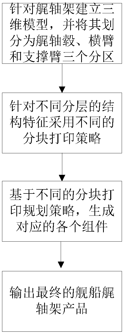
[0028] figure 1 It is the overall process flow chart of the 3D printing manufacturing process of the ship stern shaft frame arc fuse constructed according to the present invention. Such as figure 1 As shown, the specific process flow chart of the 3D printing manufacturing process of the ship stern shaft frame arc fuse constructed according to the present invention is shown. Compared with the ...


PUM

PropertyMeasurementUnit
diameteraaaaaaaaaa

Abstract

The invention belongs to the technical field of ship tail shaft bracket manufacturing technologies, and discloses a ship tail shaft bracket electric arc wire fusing 3D printing manufacturing method. The method comprises the steps that (1) a corresponding three-dimensional model is built for a tail shaft bracket and is divided into three partitions corresponding to a tail shaft hub, a transverse arm and a supporting arm; (2) according to the different partitions, printing paths are planned and designed based on different principles, and a tail shaft hub printing path with all layers in ring shapes, a transverse arm printing path with all layers in rectangle shapes and a supporting arm printing path with all layers in rectangle shapes are obtained; and (3) according to the obtained differentmanufacturing paths, the electric arc wire fusing 3D printing manufacturing technology is adopted for conducting corresponding molding machining. The invention further discloses a corresponding shiptail shaft bracket product. By means of the method and the product, the problems that in the traditional ship tail shaft bracket manufacturing process, a die model is difficult, and the molding pieceperformance is poor are solved, and a new method and thinking are provided for manufacturing the tail shaft bracket.

Description

technical field [0001] The invention belongs to the technical field related to the preparation process of the ship stern shaft frame, and more specifically relates to a 3D printing manufacturing method of the ship stern shaft frame arc fuse and its products. Background technique [0002] The stern shaft frame is an important structural part of a large ship. It is mainly used to support the high-speed rotating screw propeller to ensure that the ship can work normally and stably. The stern shaft frame is subjected to the interaction of various unbalanced forces such as the gravity of the propeller and the rotational force of the propeller when the ship is moving, so the stern shaft frame must have sufficient strength and rigidity. [0003] However, the stern shaft frame has the characteristics of complex shape, large size, and difficulty in overall casting. In traditional manufacturing, the three parts of the stern shaft frame are usually cast separately, and then tailor-weld...

Claims


Application Information

Patent Timeline
Patent Type & Authority Applications(China)
IPC IPC(8): B23K9/04B23K9/235
CPCB23K9/04B23K9/235
Inventor 余圣甫宋守亮何天英代轶励史玉升
Owner HUAZHONG UNIV OF SCI & TECH
Why Eureka
Try Eureka