Numerical-control machining equipment for machining shaft bushings

A technology of processing equipment and processing shafts, which is applied in the direction of metal processing equipment, metal processing, metal processing machinery parts, etc., can solve the problems of low automation, low efficiency, troublesome clamping, etc., and achieve continuous automatic feeding and automatic clamping, Improve work efficiency and avoid the effect of manual clamping

Active Publication Date: 2018-12-11
CHONGQING IND POLYTECHNIC COLLEGE
View PDF16 Cites 11 Cited by
  • Summary
  • Abstract
  • Description
  • Claims
  • Application Information

AI Technical Summary

Problems solved by technology

[0003] First, the existing step outer wall surface (N-1, N-2), the threaded inner hole (N-3) and the radial hole (N-4) are divided into different machine tools one by one. Process processing, there are problems such as multiple clamping, low automation, low efficiency, low precision, and high cost
[0004] Second, the existing above-mentioned shaft sleeves are manually loaded and clamped one by one, which has the problems of low efficiency and troublesome clamping

Method used


Image

  • Numerical-control machining equipment for machining shaft bushings
  • Numerical-control machining equipment for machining shaft bushings
  • Numerical-control machining equipment for machining shaft bushings

Examples


Embodiment Construction

[0023] Below in conjunction with accompanying drawing and embodiment the present invention will be further described:

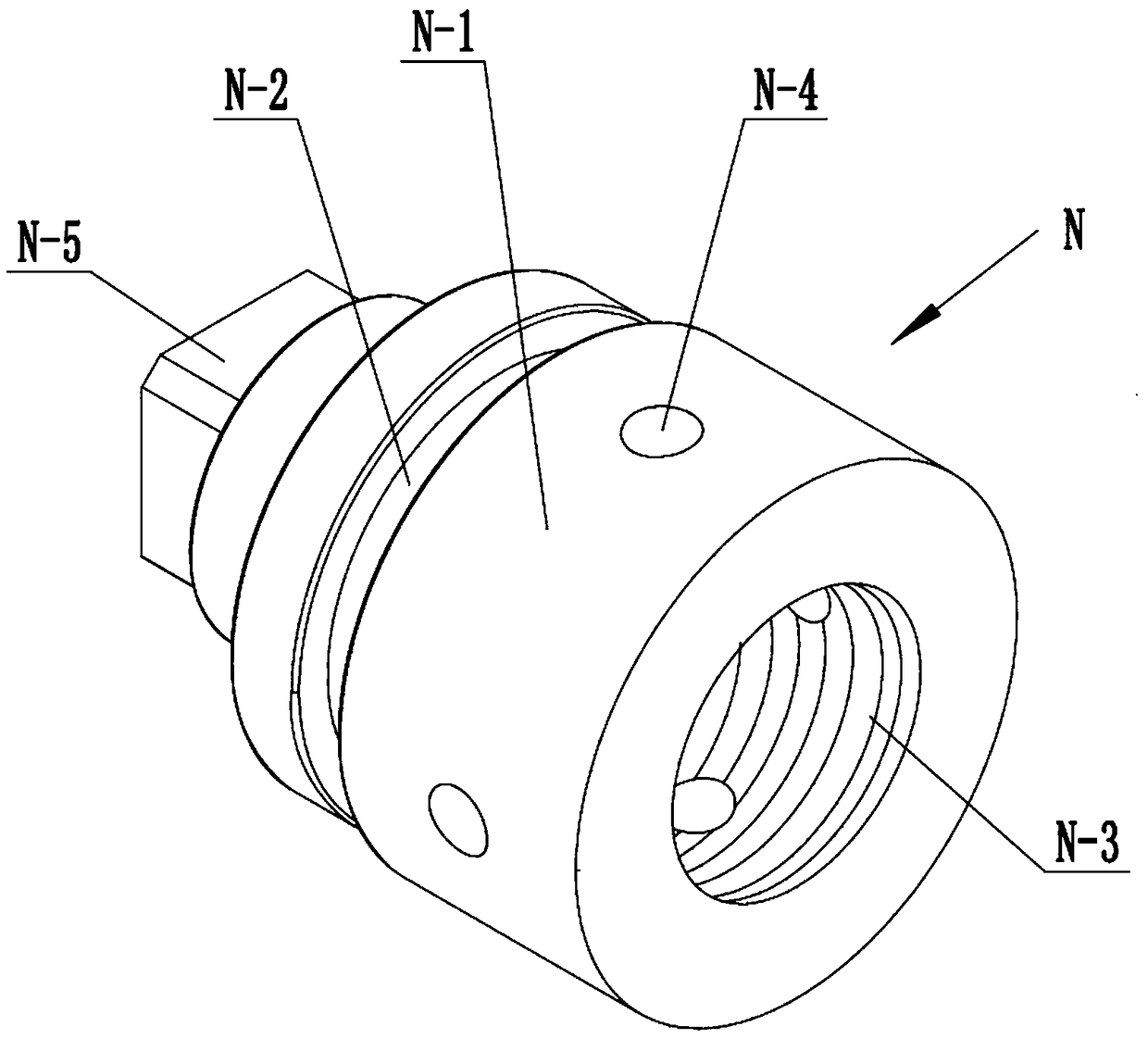
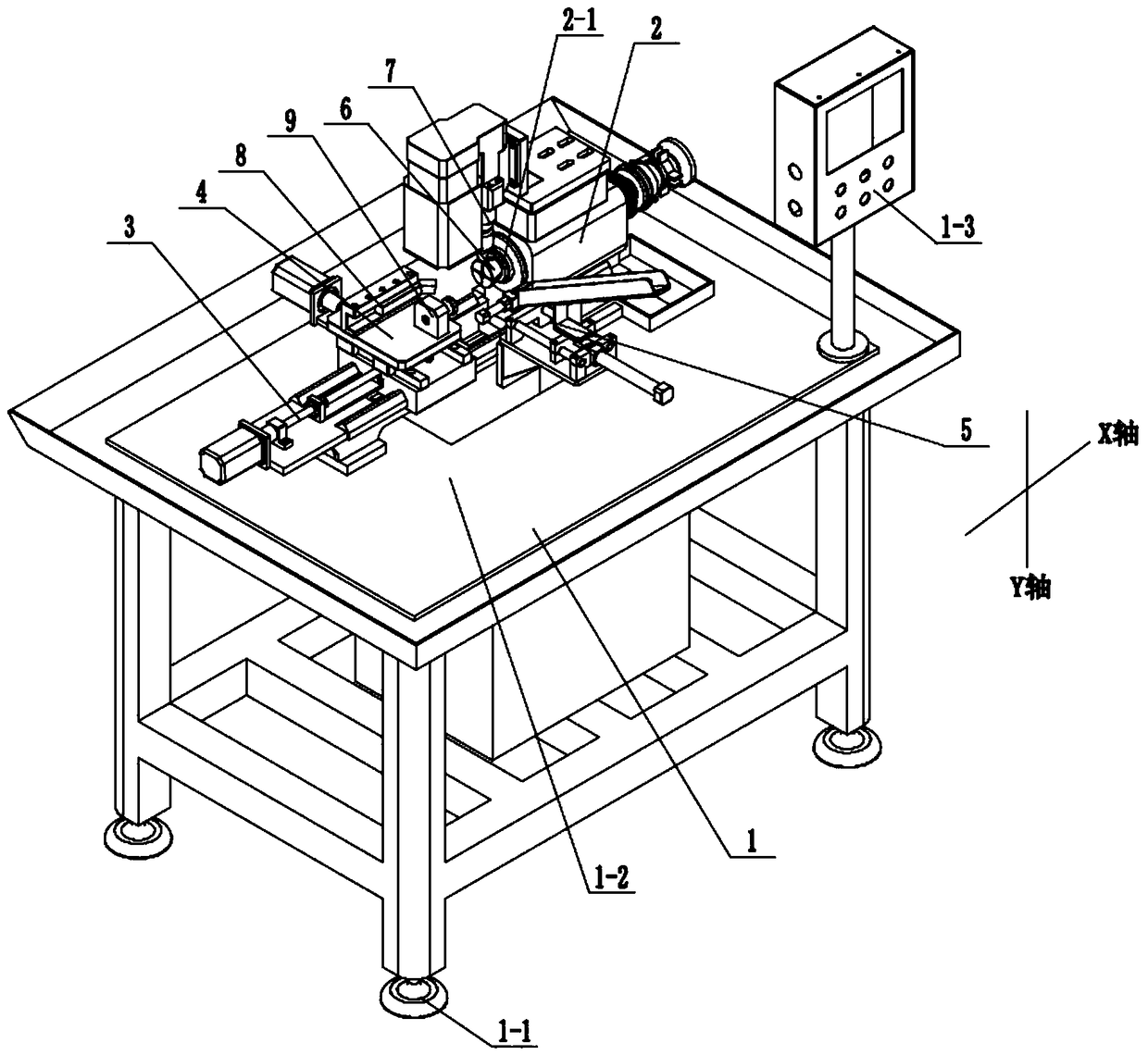
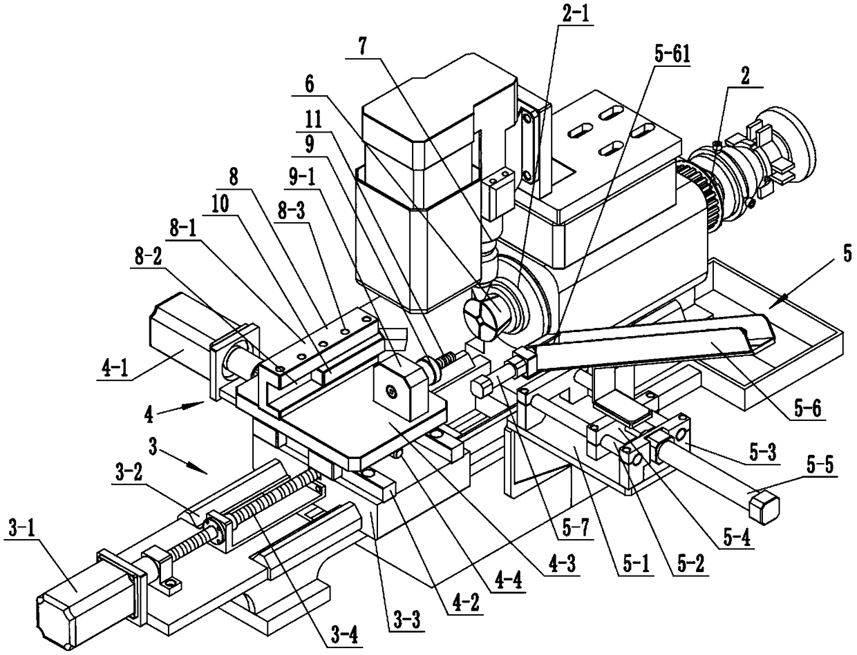
[0024] see Figure 1-7 , a kind of numerical control machining equipment for machining bushings, comprising a frame 1, a spindle box 2, an X-axis feed mechanism 3, a Y-axis feed mechanism 4, a bushing feeding mechanism 5, a bushing fixture 6, a drilling machine 7; the headstock 2 and the X-axis feed mechanism 3 are arranged on both sides of the frame 1 along the X-axis; the sleeve fixture 6 is arranged on the main shaft 2-1 of the headstock 2 and used For the clamping of the shaft sleeve N to be processed.

[0025]The X-axis feed mechanism 3 includes a first servo motor 3-1, an X-axis guide rail 3-2, an X-axis sliding seat 3-3, and an X-axis screw rod 3-4. The X-axis sliding seat 3-3 passes through the X-axis The guide rail 3-2 is slidingly connected with the frame 1, the X-axis screw rod 3-4 is in transmission connection with the X-axis slide seat 3-3, and...


PUM


Abstract

The invention discloses numerical-control machining equipment for machining shaft bushings. The numerical-control machining equipment is characterized by comprising a rack, a spindle box, an X-axis feeding mechanism, a Y-axis feeding mechanism, a bushing feeding mechanism, a bushing clamp and a drilling machine; the bushing clamp is arranged on the spindle of the spindle box and is used for clamping the bushings to be machined; the X-axis feeding mechanism comprises a first servo motor, an X-axis guide rail, an X-axis sliding seat and an X-axis threaded rod; the Y-axis feeding mechanism comprises a second servo motor, a Y-axis guide rail, a Y-axis sliding seat and a Y-axis threaded rod; the bushing feeding mechanism comprises a feeding base, a Y-axis guiding rod, a guiding-rod support, a feeding sliding seat, a Y-axis driving cylinder, a feed slot and an X-axis pushing cylinder; the drilling machine is located above the bushing clamp; a turning tool rest and a tap holder are arranged on the Y-axis sliding seat. By the arrangement, a series of automatic machining of stepped outer wall surfaces, inner threaded holes, radial holes and the like on the bushings can be achieved, workingefficiency can be increased by times, high machining precision is achieved, and production cost is greatly reduced.

Description

technical field [0001] The invention relates to a numerical control processing device, in particular to a numerical control processing device for processing shaft sleeves. Background technique [0002] see figure 1 , as an upper bushing of an automobile chassis transmission assembly, the bushing has a stepped outer wall surface (N-1, N-2), a threaded inner hole (N-3), a radial hole (N-4) and a rectangular portion (N-5). And in existing production and processing, there are following deficiencies and analyze as follows: [0003] First, the existing step outer wall surface (N-1, N-2), the threaded inner hole (N-3) and the radial hole (N-4) are divided into different machine tools one by one. Process processing, there are problems such as multiple clamping, low automation, low efficiency, low precision, and high cost. [0004] Second, the existing above-mentioned shaft sleeves are manually loaded one by one and manually clamped, which has the problems of low efficiency and t...

Claims


Application Information

Patent Timeline
Patent Type & Authority Applications(China)
IPC IPC(8): B23P23/02B23Q1/25B23Q3/12B23Q5/36B23Q5/40B23Q7/08
CPCB23P23/02B23Q1/25B23Q3/12B23Q5/36B23Q5/40B23Q7/08B23Q2703/10
Inventor 刘虹
Owner CHONGQING IND POLYTECHNIC COLLEGE
Why Eureka
Try Eureka