Micro-part pose automatic alignment device and method

An automatic alignment and micro-parts technology, applied in image data processing, program control manipulator, image data processing, etc., can solve problems such as low alignment efficiency and complicated alignment process

Active Publication Date: 2018-12-11
INST OF AUTOMATION CHINESE ACAD OF SCI
View PDF9 Cites 20 Cited by
  • Summary
  • Abstract
  • Description
  • Claims
  • Application Information

AI Technical Summary

Problems solved by technology

[0005] In order to solve the above-mentioned problems in the prior art, that is, in order to solve the problem that the alignment process of the existing micro-part pose alignment method is relatively complicated and the alignment efficiency is low, on the one hand, the present invention provides an automatic micro-part pose alignment Alignment method, the pose automatic alignment method includes: Step S1000: Obtain the deviation between the current image feature of the second micro part in the micro vision system and the expected image feature; Step S2000: Determine whether the deviation is smaller than the preset Threshold value, if yes, it indicates that the second micro-part is aligned with the first micro-part, if not, execute step S3000; step S3000: calculate the attitude adjustment amount and position adjustment amount of the end effector based on the deviation; step S4000: according to the Adjust the pose of the end effector by the attitude adjustment amount and the position adjustment amount so as to change the pose of the second micro-part and return to step S1000; wherein the position adjustment amount includes an adjustment for position alignment amount and the compensation amount used to compensate the position offset caused by the attitude adjustment

Method used


Image

  • Micro-part pose automatic alignment device and method
  • Micro-part pose automatic alignment device and method
  • Micro-part pose automatic alignment device and method

Examples


Embodiment Construction

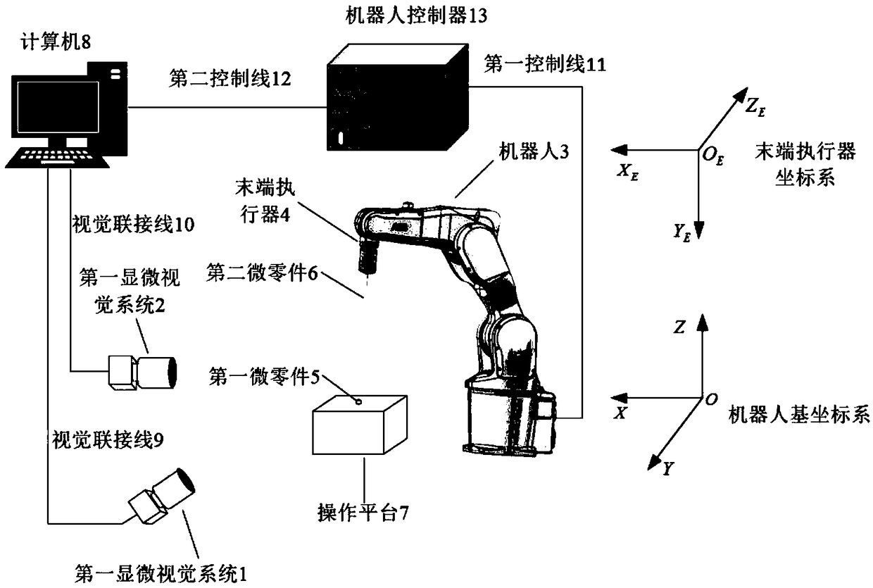
[0038] Those skilled in the art should understand that the embodiments in this section are only used to explain the technical principle of the present invention, and are not used to limit the protection scope of the present invention. For example, although the present invention is described in conjunction with the micro-part automatic alignment device using a six-degree-of-freedom robot, those skilled in the art can make adjustments to it as needed to adapt to specific applications, such as the present invention The automatic alignment method of the micro-part pose can also be applied to the automatic alignment device of the micro-part pose using a seven-degree-of-freedom robot.

[0039] It should be noted that, in the description of the present invention, the terms "first" and "second" are only used for description purposes, and cannot be understood as indicating or implying relative importance, and thus should not be construed as limiting the present invention.

[0040] In a...


PUM


Abstract

The invention belongs to the technical field of micro-assembly, and particularly provides a micro-part pose automatic alignment device and method. The pose automatic alignment method comprises the following steps that S1000, a deviation of a current image characteristic and an expected image characteristic of a second micro-part in a microscopic vision system is obtained; S2000, the deviation is judged whether smaller than a preset threshold value or not, if yes, the second micro-part is aligned with the first micro-part, and if not, S3000 is executed; S3000, a posture adjustment amount and aposition adjustment amount of an end effector is calculated based on the deviation; and S4000, the pose of the end effector is adjusted according to the posture adjustment amount and the position adjustment amount and returning to the S1000 is carried out, wherein the position adjustment amount comprises an adjustment amount for position alignment and a position offset compensation amount caused by compensating the posture adjustment. According to the device and method, by means of closed-loop control and position compensation, alignment errors are reduced, alignment precision and alignment efficiency are improved, and the problems that an existing micro-part pose alignment method is complex in operation process and low in alignment efficiency are solved.

Description

technical field [0001] The invention belongs to the technical field of micro-assembly, and specifically provides a micro-part pose automatic alignment device and a method thereof. Background technique [0002] With the rapid development of micro-electromechanical systems, the research on micro-assembly technology is getting more and more in-depth. Advanced micro-miniature parts assembly technology is of great significance in improving the assembly quality of micro-miniature parts, shortening the cycle, and reducing production costs. [0003] At present, the micro-assembly process is often complicated, and the degree of automation is generally not high. Microassembly efficiency is low due to the lack of fast and accurate methods for pose alignment of micro-parts. Previous studies mainly fall into the following two categories: one uses microscopic vision systems with different magnifications to achieve alignment, but the process is complex and requires high system hardware (s...

Claims


Application Information

Patent Timeline
Patent Type & Authority Applications(China)
IPC IPC(8): B25J9/16B23P19/10G06T1/00G06T7/73
CPCB23P19/10B25J9/1605B25J9/1687B25J9/1697G06T1/0014G06T7/74G06T2207/30164
Inventor 马燕芹徐德张大朋刘希龙
Owner INST OF AUTOMATION CHINESE ACAD OF SCI
Why Eureka
Try Eureka