Al technical title is built by PatSnap Al team. It summarizes the technical point description of the patent document.
A technology of wood chips and support blocks, which is applied in wood processing appliances, bark area/debris/dust/waste removal, manufacturing tools, etc., can solve the problem of increasing power consumption and waste, inconvenience of one-time molding of wood chips, and inability to achieve energy saving and environmental protection and other problems, to achieve the effect of reducing the working process, saving working time and compact structure
Active Publication Date: 2018-12-11
曾金玉
View PDF10 Cites 5 Cited by
Summary
Abstract
Description
Claims
Application Information
AI Technical Summary
This helps you quickly interpret patents by identifying the three key elements:
Problems solved by technology
Method used
Benefits of technology
Problems solved by technology
[0002] In the process of wood processing, a large amount of wood chips will be generated due to cutting. In the post-processing process of wood chips, they can be used as by-products such as supporting density boards. In the process of collecting wood chips, they need to be briquetted. The existing briquettes The device is not convenient for quantitative control of the blanking, and manual operation control is required, which increases the labor intensity of the workers, and is not convenient for one-time molding of wood chips, and after molding, multiple processes are required to send out, which is laborious and labor-intensive, increasing the working process. Wasted working time, increased consumption and waste of electric energy, unable to achieve energy conservation and environmental protection
Method used
Image
Click on the blue label to locate the original text in one second.
Reading with bidirectional positioning of images and text.
Examples
Embodiment Construction
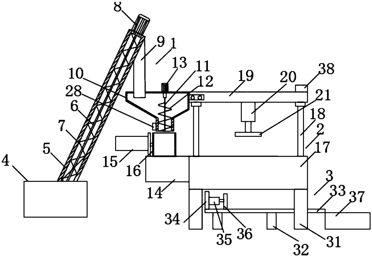
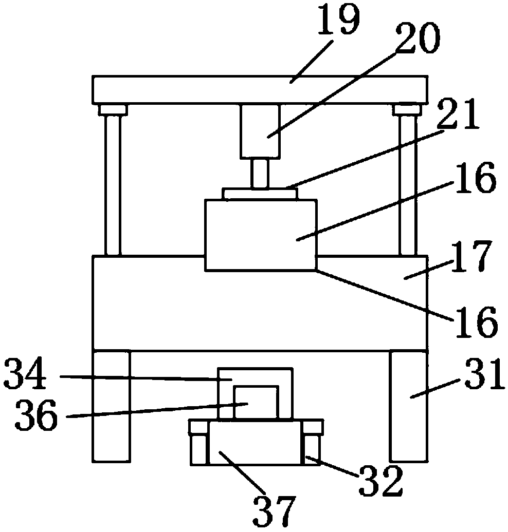
[0019] Such as Figure 1-3 As shown, this specific embodiment adopts the following technical solutions: a briquetting device for sawdust recycling, including a feeding mechanism 1, a pressing mechanism 2 and a receiving mechanism 3, and a pressing mechanism 2 is provided below the feeding mechanism 1, The bottom of the pressing mechanism 2 is provided with a receiving mechanism 3, and the feeding mechanism 1 is composed of a storage box 4, a feeding pipe 5, a central shaft 6, a first rotating blade 7, a feeding motor 8, and a feeding pipe 9. , feeding box 10, transmission shaft 11, second rotating blade 12, feeding motor 13, support block 14, feeding cylinder 15 and feeding box 16, the fixed connection ring at the top of the storage box 4 has a feeding pipe 5. A central shaft 6 is rotatably connected between the top and the bottom of the inner wall of the feeding pipe 5, and the outer side of the central shaft 6 is fixedly connected with a first rotating blade 7, and the outer...
PUM
Abstract
The invention discloses a compression device for wood chip recovery. The compression device for wood chip recovery comprises a feeding mechanism, a pressing mechanism and a receiving mechanism, wherein the pressing mechanism is arranged below the feeding mechanism; the receiving mechanism is arranged below the pressing mechanism; and the feeding mechanism is composed of a storage box, a conveyingpipe, a central shaft, a first rotary blade, a conveying motor, an unloading pipe, an unloading box, a transmission shaft, a second rotary blade, an unloading motor, a support block, a feeding cylinder and a transport box. The compression device for wood chip recovery is compact in structure, and facilitates recovery and use for wood chips; through the arrangement for the feeding mechanism and control over rotation time of the unloading motor and the second rotary blade, quantitative control over unloading is facilitated, and manual operation control is not required, so that the labor intensity of workers is lowered; through the arrangement for a compression mechanism, one-process forming for the wood chips is facilitated, and the wood chips are directly conveyed out after being formed, the operation is convenient and rapid, and the working procedures are reduced, so that the working time is saved, consumption and waste for electric energy are reduced, and energy conservation and environment protection are realized; and the compression device for wood chip recovery is more flexible in structure and high in practicability.
Description
Technical field: [0001] The invention relates to the technical field of garden machinery, in particular to a briquetting device for recycling sawdust. Background technique: [0002] In the process of wood processing, a large amount of wood chips will be generated due to cutting. In the post-processing process of wood chips, they can be used as by-products such as supporting MDF. In the process of collecting wood chips, they need to be briquetted. The existing briquettes The device is not convenient for quantitative control of the blanking, and manual operation control is required, which increases the labor intensity of the workers. It is not convenient to realize one-time molding of wood chips, and after molding, multiple processes are required to send out, which is laborious and labor-intensive, increasing the working process. Working time is wasted, the consumption and waste of electric energy are increased, and energy saving and environmental protection cannot be realized...
Claims
Application Information
Patent Timeline
Application Date:The date an application was filed.
Publication Date:The date a patent or application was officially published.
First Publication Date:The earliest publication date of a patent with the same application number.
Issue Date:Publication date of the patent grant document.
PCT Entry Date:The Entry date of PCT National Phase.
Estimated Expiry Date:The statutory expiry date of a patent right according to the Patent Law, and it is the longest term of protection that the patent right can achieve without the termination of the patent right due to other reasons(Term extension factor has been taken into account ).
Invalid Date:Actual expiry date is based on effective date or publication date of legal transaction data of invalid patent.