A biomimetic wave leading edge wing tip winglet device

A leading edge and wing tip technology, applied in the field of bionic wave leading edge winglet devices, can solve problems such as hindering the application of winglets, high cost of mold manufacturing, unsuitable for large angles of attack, etc. Strengthen the effect of momentum exchange and lift coefficient improvement

Active Publication Date: 2018-12-11
XI AN JIAOTONG UNIV
View PDF7 Cites 4 Cited by
  • Summary
  • Abstract
  • Description
  • Claims
  • Application Information

AI Technical Summary

Problems solved by technology

[0003] Aiming at the technology of "improving the aerodynamic performance of the wing", many researchers have proposed various design schemes. At present, the integrated winglet commonly used in large and medium-sized civil aircraft has the advantages of high mold manufacturing cost, low aerodynamic efficiency, Problems such as heavy component weight and insufficient reliability
Generally, counterweights need to be installed on the wingtips to offset the flutter characteristics and reinforce the extra structural weight. The above shortcomings hinder the application of winglets on small low-speed aircraft
For example, the patent CN206797703U proposes a winglet of an aircraft, which is formed by bending an aluminum alloy material and fixed on the wingtip by screwing. Suitable for high angle of attack

Method used


Image

  • A biomimetic wave leading edge wing tip winglet device
  • A biomimetic wave leading edge wing tip winglet device
  • A biomimetic wave leading edge wing tip winglet device

Examples


Embodiment Construction

[0023] The present invention will be described in detail below in conjunction with the accompanying drawings.

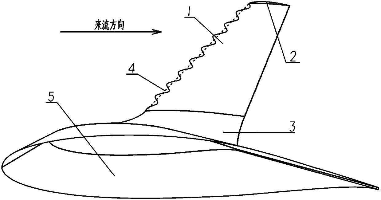
[0024] see figure 1 and figure 2 , the bionic wave leading edge winglet device of the present invention is made of fin leading edge section 1, top rectifying section 2 and transition section 3, and fin leading edge section 1, top rectifying section 2 and transition section 3 are all made of thickness 0.5mm The ~2mm aluminum alloy plate is bent and formed. The leading edge section 1 of the fin is a multi-section curved surface with openings at both ends. 1 is provided with a transition section 3, and the transition section 3 is arranged on the wing 5, the transition section 3 is a connecting part between the wing 5 and the fin leading edge section 1, and the fin leading edge section 1 and the transition section 3 pass through bolts for connection.

[0025] The fin leading edge section 1, the top rectifying section 2 and the transition section 3 are connected by bo...


PUM


Abstract

A biomimetic wave leading edge wing tip winglet device includes a fin leading edge segment, a top rectifier section and a transition section, The leading edge section of the fin is a multi-sectional curved surface with two opened ends, one side of the leading edge section of the fin is of a wave structure, the top rectifier section is fixed on the top of the leading edge section of the fin to close the top of the leading edge section of the fin, the bottom of the leading edge section of the fin is provided with a transition section, and the transition section is arranged on the wing, the leading edge section of the fin, the top rectifier section and the transition section form a wing tip small wing. As that lead edge of the tip winglet forms regular bump, the uniform incoming flow can generate vortices with opposite rotational directions and high energy at high angle of attack, thereby maintaining airflow adhesion on the winglet, delay airflow separation and development, finally delaying the stall angle of attack of the wing, increasing the maximum lift coefficient, and achieving the purpose of shortening the takeoff distance.

Description

technical field [0001] The invention relates to a bionic wave leading edge winglet device. Background technique [0002] Winglets are one of the main technical means for aircraft to reduce induced drag, reduce fuel consumption and increase flight range. This is because the winglets can block the air flow from the lower surface of the wing to the upper surface, which greatly weakens the strength of the wingtip vortex, thereby reducing the downwash airflow caused by the wingtip vortex, thereby effectively weakening the airflow of the aircraft. The induced drag of the wing is widely used in passenger aircraft and transport aircraft. Installing winglets can achieve the same drag reduction effect as increasing the wingspan, but as the angle of attack increases, the airflow on the upper surface of the winglets will separate before the main wing, and then induce the separation of the main wing, which will seriously Affects the aerodynamic performance of the wing at high angles of...

Claims


Application Information

Patent Timeline
Patent Type & Authority Applications(China)
IPC IPC(8): B64C3/58B64C5/08
CPCB64C3/58B64C5/08
Inventor 张扬王鹏汪辉陈刚
Owner XI AN JIAOTONG UNIV
Why Eureka
Try Eureka