A rotor blade and an axial flow compressor

A technology for axial flow compressors and rotor blades, applied in mechanical equipment, machines/engines, liquid fuel engines, etc., can solve the problems of loss, difficult interstage leakage, high pressure difference, etc., and achieve the effect of strengthening momentum exchange

Active Publication Date: 2020-05-22
AECC COMML AIRCRAFT ENGINE CO LTD
View PDF7 Cites 0 Cited by
  • Summary
  • Abstract
  • Description
  • Claims
  • Application Information

AI Technical Summary

Problems solved by technology

With the performance requirements of the axial flow compressor, the stage pressure ratio becomes higher and higher, resulting in a higher and higher pressure difference between the stator vane discharge inlet / outlet, which makes it difficult to completely seal the interstage leakage
The airflow leaked between stages often returns to the main channel in a direction close to the vertical direction of the upstream flow, and is mixed with the boundary layer of the upstream flow, which will cause a large loss

Method used


Image

  • A rotor blade and an axial flow compressor
  • A rotor blade and an axial flow compressor
  • A rotor blade and an axial flow compressor

Examples


Embodiment Construction

[0031] The present invention will be further described below in conjunction with specific embodiment and accompanying drawing, set forth more details in the following description so as to fully understand the present invention, but the present invention can obviously be implemented in many other ways different from this description, Those skilled in the art can make similar promotions and deductions based on actual application situations without violating the connotation of the present invention, so the content of this specific embodiment should not limit the protection scope of the present invention.

[0032] have to be aware of is, Figure 1 to Figure 8 All are for example only, and they are not drawn in accordance with the same scale conditions, and should not be taken as limitations on the protection scope of the actual claims of the present invention.

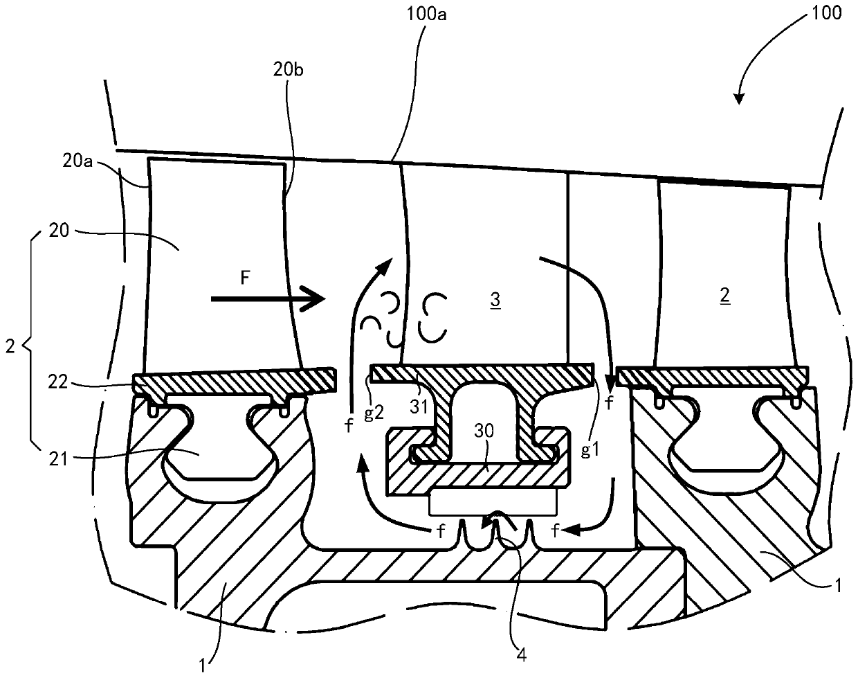
[0033] first reference figure 1 , the axial flow compressor 100 of the gas turbine includes a rotor and a stator. The ...


PUM


Abstract

An object of the invention to provide a rotor blade and an axial-flow compressor. The rotor blade is suitable for being mounted on a rotor drum of a rotor of the axial-flow compressor, and includes ablade body, a tenon and a margin plate; for two rotor blades that can be circumferentially adjacent to the rotor drum, a first groove structure of a suction surface portion of the margin plate of oneof the rotor blades and a second groove structure of a pressure surface portion of the margin plate of the other rotor blade are combined and spliced to form a flow channel wall surface between the two rotor blades disposed adjacently in the circumferential direction, and the flow channel wall surface is provided with a plurality of grooves uniformly distributed in a wave shape in the circumferential direction; the grooved extend in a direction from a leading edge to a trailing edge, and the depth of the grooves gradually increases along an extending direction; and end points at which the grooves extend are located on the side wall surface of the margin plate. Presence of the grooves makes the thickness of a boundary layer reduce, thereby reducing a blending and mixing area of interstage leakage and the boundary layer, and so, pneumatic loss caused by the interstage leakage is reduced, and the compressor efficiency and surge margin are improved.

Description

technical field [0001] The invention relates to a rotor blade and an axial flow compressor. Background technique [0002] The axial flow compressor of a gas turbine consists of a rotor and a stator. The rotor is an assembly that rotates at high speed to do work on the airflow, and is used to do work on the gas entering the axial flow compressor. The rotor includes rotor blades. The stator is attached to the casing, including the stator blades. In order to prevent the high-speed rotating rotor blade from colliding with the adjacent stator blade, there is a gap between the edge plate of the rotor blade and the edge plate of the stator blade in the axial direction, which is called the interstage gap. Since there is a certain static pressure difference at the inlet / outlet of the stator blade row, under the effect of this static pressure difference, there will be airflow near the blade crown of the stator blade from the downstream interstage gap of the stator blade through the ...

Claims


Application Information

Patent Timeline
Patent Type & Authority Patents(China)
IPC IPC(8): F04D29/38F04D29/66
CPCF04D29/324F04D29/666F04D29/667
Inventor 闫转运南长峰樊琳曾瑞慧杨俊
Owner AECC COMML AIRCRAFT ENGINE CO LTD
Why Eureka
Try Eureka