A method for assembling a steel box girder of a curve bridge by a sliding method

A construction method and technology of steel box girders, applied in bridges, bridge construction, erection/assembly of bridges, etc., can solve problems such as low safety, broken traction cables, unfavorable curve bridge construction, etc., and achieve strong applicability and outstanding effects Effect

Inactive Publication Date: 2018-12-11
ROAD & BRIDGE INT +1
View PDF6 Cites 21 Cited by
  • Summary
  • Abstract
  • Description
  • Claims
  • Application Information

AI Technical Summary

Problems solved by technology

[0004] The current traction slip method mainly uses a hoist or a hydraulic jack to pull the steel box girder to slide through the traction cable. Due to the high sliding resistance, there is a high requirement for the strength of the traction cable material. During the construction, the traction cable breaks and the safety Low; at the same time, in order to reduce the sliding resistance, the slide rail needs to be treated, usually by applying lubricating oil or laying PTFE board on the rail. The specific construction is laborious and laborious, and the effect is not good in actual engineering
In addition, because the traction force is transmitted in a straight line, the current traction-slip method is not conducive to the construction of curved bridges

Method used


Image

  • A method for assembling a steel box girder of a curve bridge by a sliding method
  • A method for assembling a steel box girder of a curve bridge by a sliding method
  • A method for assembling a steel box girder of a curve bridge by a sliding method

Examples


Embodiment Construction

[0026] Hereinafter, specific embodiments of the present invention will be described in conjunction with the accompanying drawings.

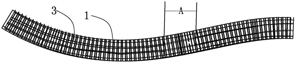
[0027] A bridge constructed by the applicant is located in the urban area, the bridge spans the subway, the on-site passenger flow is dense, and the bridge line is S-shaped. Since the ground load above the subway station is required not to exceed 20KN / ㎡, and the steel box girder of this bridge is 6000mm long, 29500mm wide, and weighs more than 20 tons per linear meter, if the hoisting method is used, the hoisting construction will be carried out at the top of the subway station. The concentrated ground load will far exceed the specified limit, so the hoisting method cannot be used for construction, and the slip method should be considered. However, the safety of the traditional sliding method is low, and the passenger flow is dense near the subway station. Considering the safety, the traditional sliding method should not be adopted, and the bridg...


PUM


Abstract

A method for assembling a steel box girder of a curve bridge by a sliding method includes setting up two rows of supports along a bridge direction, and setting up cross beams on each row of supports in a transverse bridge direction. According to the bridge curve, laying a track on the crossbeams of each support along the bridge direction, arranging a wheel-rail type beam transporter on the track,lifting a section of steel box girder to be installed on the beam transporter by a crane, driving the beam transporter to travel along the track, and transporting the steel box girder to the design installation position; Two jacks are respectively arranged on the bracket cross beams on both sides of the steel box girder on the outside of each track, and the jacks are activated to lift the steel box girder upward, so that the steel box girder leaves the top surface of the beam transporting vehicle, and the beam transporting vehicle returns to transport the next section of the steel box girder.The invention improves the traditional sliding method and is suitable for the installation and construction of the steel box girder of a curved bridge.

Description

technical field [0001] The invention belongs to the field of bridge engineering construction, and relates to a technology applied to the on-site assembly construction of steel box girders, in particular to a sliding method assembly construction method of steel box girders of curved bridges. Background technique [0002] The traditional installation and construction of steel box girder of steel structure bridge is mainly the hoisting method. The steel box girder is directly hoisted to the installation position with a large crane. The equipment could not be unfolded, and the steel box girder could not be constructed by the hoisting method, so the traction-sliding method came into being. [0003] The traction slip method construction refers to erecting a bracket between the area where the hoisting equipment can be deployed and the installation area of ​​the steel box girder, setting slide rails on the bracket, first hoisting the steel box girder to the bracket with a hoisting m...

Claims


Application Information

Patent Timeline
Patent Type & Authority Applications(China)
IPC IPC(8): E01D21/00E01D2/04
CPCE01D2/04E01D21/00
Inventor 田连民阎王虎李川渠凯侯兆隆浦长见李伯昊邱伟超张雨宾赵翔魏涛
Owner ROAD & BRIDGE INT
Why Eureka
Try Eureka