
Bolt connecting prefabricated concrete frame structure

A prefabricated concrete and prefabricated concrete slab technology, applied in building components, building structure, earthquake-proof and other directions, can solve the problems of prefabricated component steel bar positioning error and high requirements for grouting equipment, affecting the overall performance of the frame structure, and grouting is not compact, etc. The effect of fast construction, easy hoisting and positioning, and convenient grouting

Inactive Publication Date: 2018-12-11
TONGJI UNIV
View PDF11 Cites 0 Cited by
  • Summary
  • Abstract
  • Description
  • Claims
  • Application Information

AI Technical Summary

Problems solved by technology

Both of the above two connection methods require pressure grouting on site, which requires high positioning error of prefabricated steel bars and grouting equipment, and problems such as incomplete grouting are prone to occur during construction, which affects the overall performance of the frame structure

Method used


Image

  • Bolt connecting prefabricated concrete frame structure
  • Bolt connecting prefabricated concrete frame structure
  • Bolt connecting prefabricated concrete frame structure

Examples


Embodiment 1

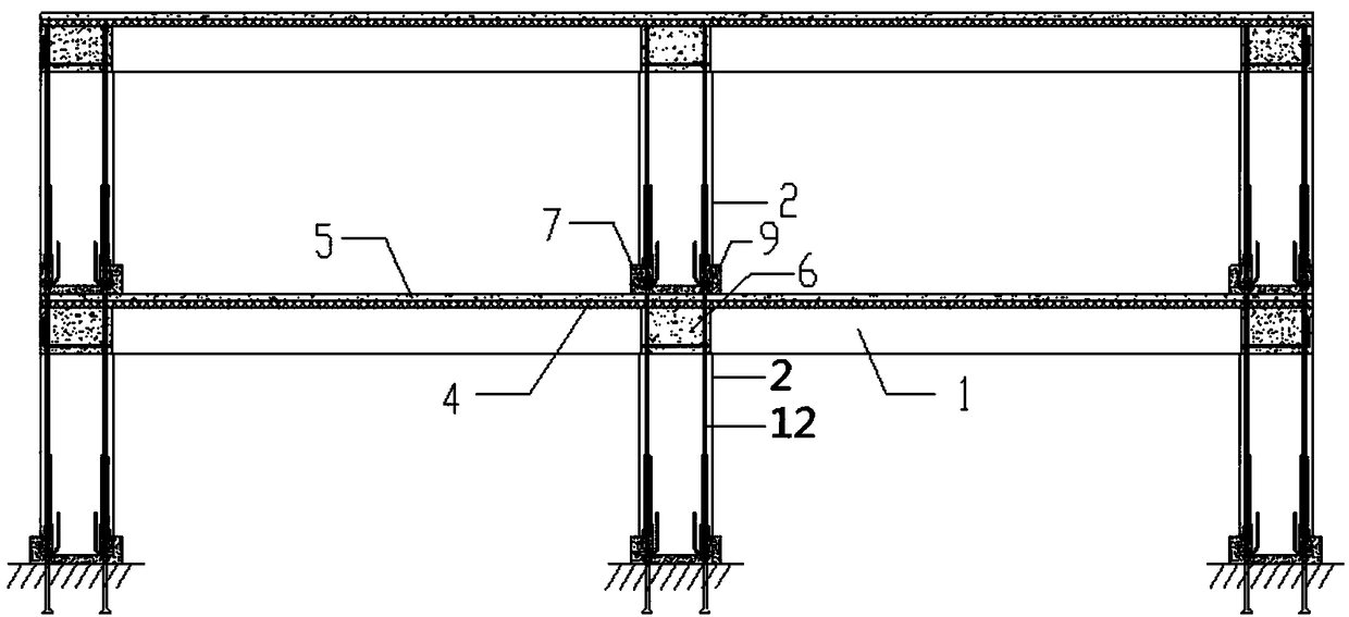
[0030] like figure 1 As shown, the bolt-connected precast concrete frame structure includes a plurality of precast concrete columns 2, a plurality of precast concrete beams 1, a plurality of precast concrete slabs 4, a post-cast concrete laminate layer 5, a plurality of post-cast concrete beam connection node areas 6 and Column foot grouting area 9.

[0031] The plurality of precast concrete columns 2 at the bottom are distributed in a grid shape, and the plurality of precast concrete columns 2 are arranged vertically on the ground in rows, each row is parallel to each other, and the positions of adjacent rows and adjacent precast concrete columns 2 are aligned of.

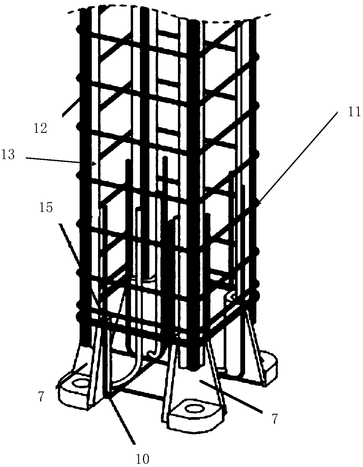
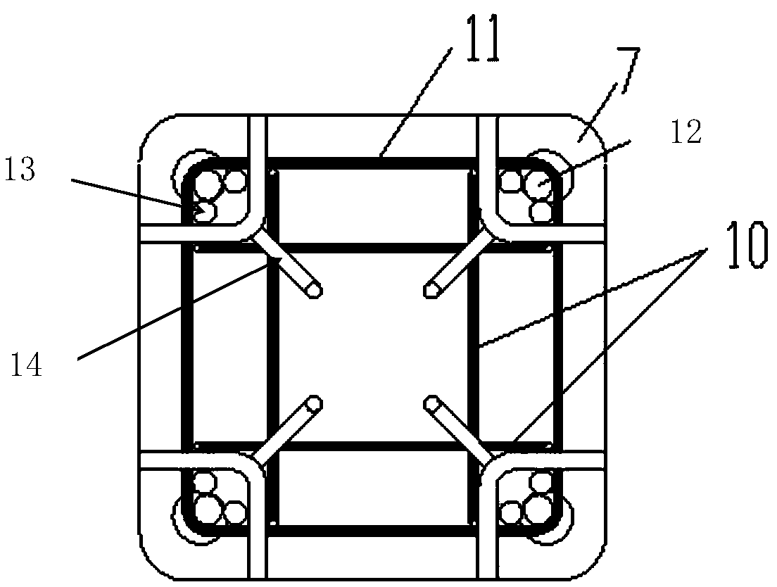
[0032] like figure 2 , 3 As shown, the prefabricated concrete column 2 includes 4 connectors 7, 4 U-shaped stirrups 10, multiple transverse stirrups 11, 4 longitudinal reinforcements 12, 8 lapping reinforcements 13, 4 positioning reinforcements 14, 2 Additional stirrups 15.

[0033] In the embodiment, the pr...

Embodiment 2

[0052] The present embodiment is the same as the other structure of the first embodiment, except that the ends of the four longitudinal steel bars 12 exposed to the concrete in the first embodiment are replaced by pre-embedded high-strength screw rods.

[0053] The top area of ​​the high-strength screw is provided with external threads.

[0054] Function and effect of embodiment


PUM


Abstract

The invention discloses a bolt connecting prefabricated concrete frame structure which comprises a plurality of prefabricated concrete columns, a plurality of prefabricated concrete beams, a pluralityof prefabricated concrete plates, post-cast concrete overlapping layers, a plurality of post-cast concrete beam connecting joint areas and column leg grouting areas, the bottom prefabricated concretecolumns are vertically arranged on the ground according to lines, each prefabricated concrete beam is arranged on two adjacent prefabricated concrete columns of each line, the prefabricated concreteplates are arranged on two opposite prefabricated concrete beams, the post-cast concrete overlapping layers are arranged on the prefabricated concrete plates, concrete beam connecting joint area modules are mounted in the post-cast concrete beam connecting joint areas to cast a connecting joint area, a plurality of connectors of the upper prefabricated concrete columns are connected with a plurality of upper bolts of the lower prefabricated concrete columns through a plurality of nuts, and gaps among the upper prefabricated concrete columns and the post-cast concrete overlapping layers are grouted by the column leg grouting areas.

Description

technical field [0001] The invention belongs to the technical field of civil engineering, and in particular relates to a bolt-connected prefabricated concrete frame structure. Background technique [0002] The prefabricated concrete frame structure has fast construction speed, good quality, and can save a lot of formwork and supports. It has significant energy saving and emission reduction characteristics. At the same time, it can realize large spans and meet the requirements of users with large bays. It is a structural form that meets the needs of industrialized building development. . [0003] The connection of prefabricated columns in the existing precast concrete frame structure system usually adopts sleeve grouting connection or grout anchor lap connection. The sleeve grouting connection is to insert the reserved steel bars of the prefabricated lower column into the pre-embedded sleeve in the prefabricated upper column, and pour high-strength non-shrinking cement morta...

Claims


Application Information

Patent Timeline
Patent Type & Authority Applications(China)
IPC IPC(8): E04B1/19E04B1/98E04H9/02
CPCE04B1/19E04H9/02
Inventor 薛伟辰胡翔
Owner TONGJI UNIV
Learn More