A flexible self-expanding gas drainage drilling and sealing device and method

A gas drainage and sealing device technology, which is applied in the direction of gas discharge, safety devices, mining equipment, etc., can solve the problems of difficult ratio accurate and full mixing, strong randomness, and affect the sealing effect, so as to ensure the sealing effect , wide practicability, and simple structure

Active Publication Date: 2021-11-26
徐州海森德新材料有限公司
View PDF8 Cites 0 Cited by
  • Summary
  • Abstract
  • Description
  • Claims
  • Application Information

AI Technical Summary

Problems solved by technology

Later, polyurethane foam bags were used to fix the front and rear ends of the gas drainage pipe respectively. These methods are a step forward compared with the use of cement and cement mixture, etc., but still have the following defects: first, the two-component The materials are all artificially poured or mixed by manual kneading. The randomness is too strong, and it is difficult to achieve accurate proportioning and full mixing.
Not only greatly affects the plugging effect, but also causes a lot of waste of materials
Second, the foaming expansion of the two-component material is not restricted, and it will extend along the axial direction of the borehole, which cannot achieve an ideal sealing and sealing effect, resulting in grout leakage during grouting in the middle section, affecting the sealing effect
Third, it is impossible to achieve deep sealing
And this kind of sealing method can't achieve deep sealing anyway.
The main reasons for the above-mentioned defects are that the two types of polyurethane materials cannot be fully mixed, and the second is that there is a lack of means to deliver the materials to the operating position.

Method used


Image

  • A flexible self-expanding gas drainage drilling and sealing device and method
  • A flexible self-expanding gas drainage drilling and sealing device and method
  • A flexible self-expanding gas drainage drilling and sealing device and method

Examples


Embodiment Construction

[0024] The specific embodiment of the present invention will be further described below in conjunction with accompanying drawing:

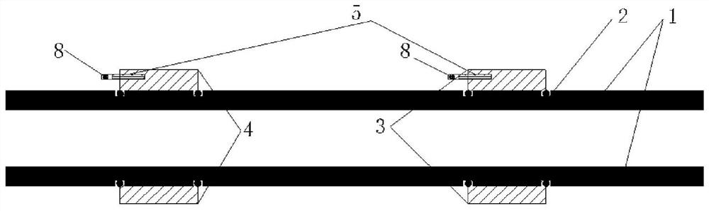
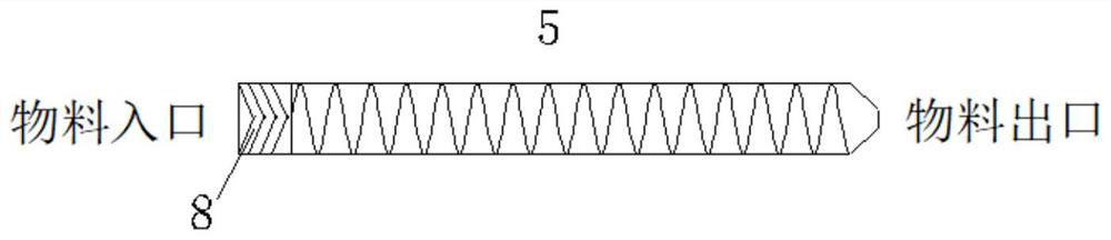
[0025] Such as figure 1 As shown, the flexible self-expanding gas drainage drilling and sealing device of the present invention includes a gas drainage pipe 1, a flexible plug and a material storage device, and the flexible plug includes a flexible plug arranged on the gas drainage pipe 1. Plug I3 and flexible plug II4, the material of the flexible plug I3 and flexible plug II4 is cylindrical high-strength non-woven fabric, the openings at both ends of the non-woven fabric are slightly larger than the outer diameter of the gas drainage pipe 1, and It is bound and fixed in the fixed groove 2 of the gas drainage pipe 1 by a clasp, and the diameter of the middle part after the expansion agent AB two materials are reacted and propped up in it should be more than 50% of the diameter of the drainage borehole; the flexible plugging The head I3 and the f...


PUM


Abstract

The invention discloses a flexible self-expanding gas drainage drilling and sealing device and method, which are suitable for underground use in coal mines. Two sections of flexible plugs at the front and rear are fixed at the fixed groove on the gas drainage pipe, and a pre-mixing pipe with a one-way valve is embedded in the two plugs respectively, and the one-way valve at the entrance of the pre-mixing pipe is connected to three When drilling and sealing the holes, connect the material bags containing the two components of A and B to the tee, squeeze the material bags to make the two-component materials automatically mix during the process of flowing through the premixing tube Evenly and then enter the flexible plug, after the predetermined amount of two-component material is injected into the front and rear flexible plugs, quickly send the gas drainage pipe together with the flexible plug to the predetermined position in the borehole, and wait for the expansion and solidification , forming a grouted airtight space. The device is simple in structure, light in weight and small in size, and can complete gas drainage and sealing holes without carrying a high-pressure pump or a water tank during use, and has wide practicability.

Description

technical field [0001] The invention relates to a gas drainage drilling and sealing device and method, in particular to a flexible self-expanding gas drainage drilling and sealing device and method for underground coal mine pre-extraction. Background technique [0002] Coal seam gas drainage is an effective means of mine gas prevention and utilization, and the sealing of drainage boreholes determines the effect of gas drainage. At present, gas drainage boreholes mostly adopt the form of "two plugs and one injection", that is, two plugs are installed in the front and back of the gas drainage pipe in the drainage borehole, and a closed space is artificially created between the two plugs, and then through The grouting pipe reserved in this confined space is injected with high-pressure grout by an external grouting pump to achieve the effect of drilling seal. For the two plugs of this sealing method, the two materials of two-component polyurethane, that is, isocyanate and combi...

Claims


Application Information

Patent Timeline
Patent Type & Authority Patents(China)
IPC IPC(8): E21B33/13E21B33/12E21F7/00
CPCE21B33/1208E21B33/13E21F7/00
Inventor 林传兵王世昌范毅伟孙鹏张夏彭李海波王諝杰
Owner 徐州海森德新材料有限公司
Why Eureka
Try Eureka