
Transient power control method for an engine that includes a compressor

An engine and compressor technology, used in engine control, machine/engine, combustion engine, etc., to solve problems such as the inability of electric drive compressors to deliver boost quickly

Pending Publication Date: 2018-12-11
FORD GLOBAL TECH LLC
View PDF0 Cites 2 Cited by
  • Summary
  • Abstract
  • Description
  • Claims
  • Application Information

AI Technical Summary

Problems solved by technology

During such conditions, the electrically driven compressor may not be able to deliver boost as quickly as desired, so that the driver may notice some hesitation in the engine delivering the requested torque

Method used


Image

  • Transient power control method for an engine that includes a compressor
  • Transient power control method for an engine that includes a compressor
  • Transient power control method for an engine that includes a compressor

Examples


Embodiment Construction

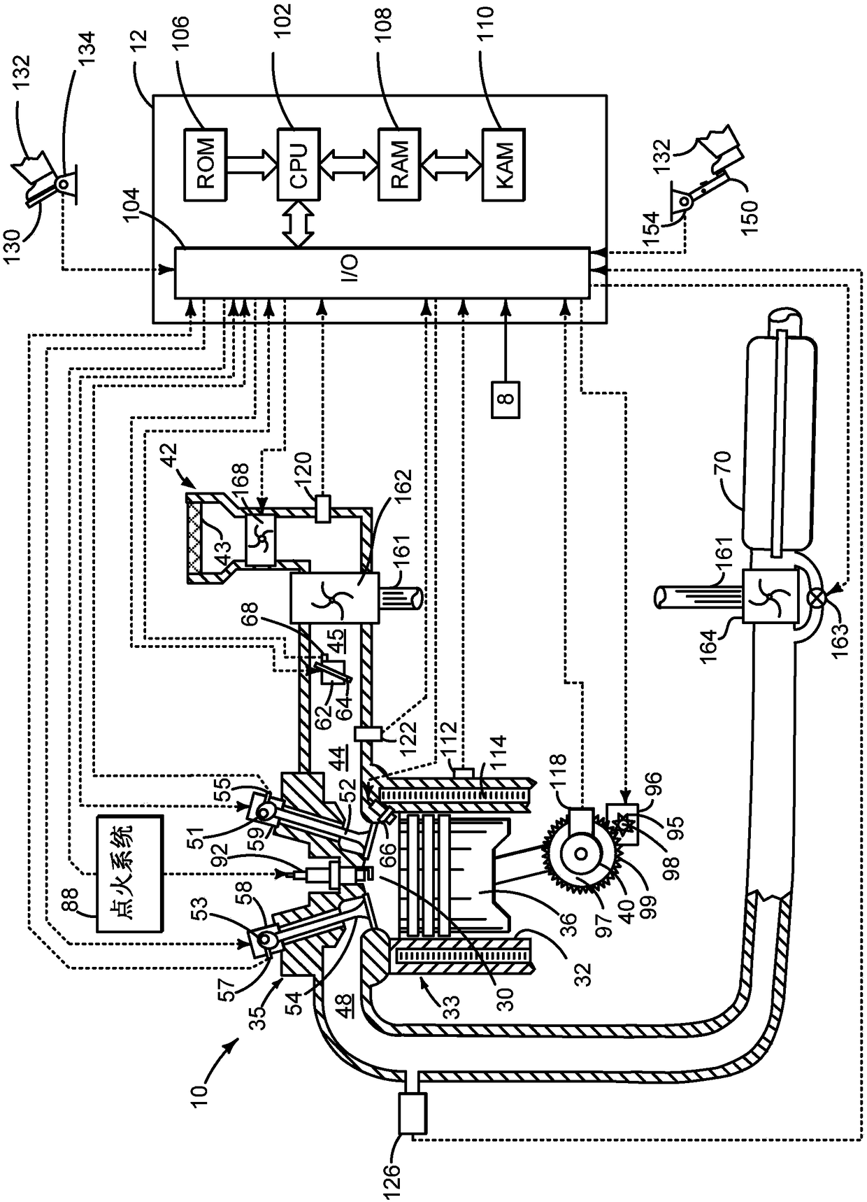
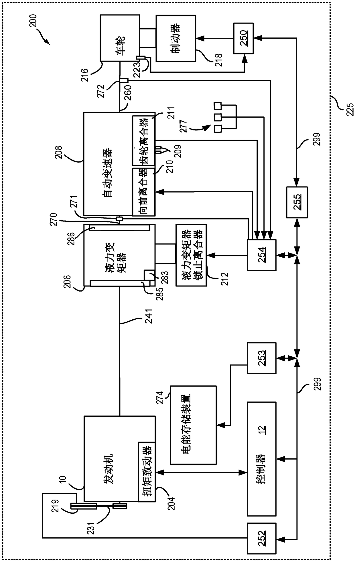
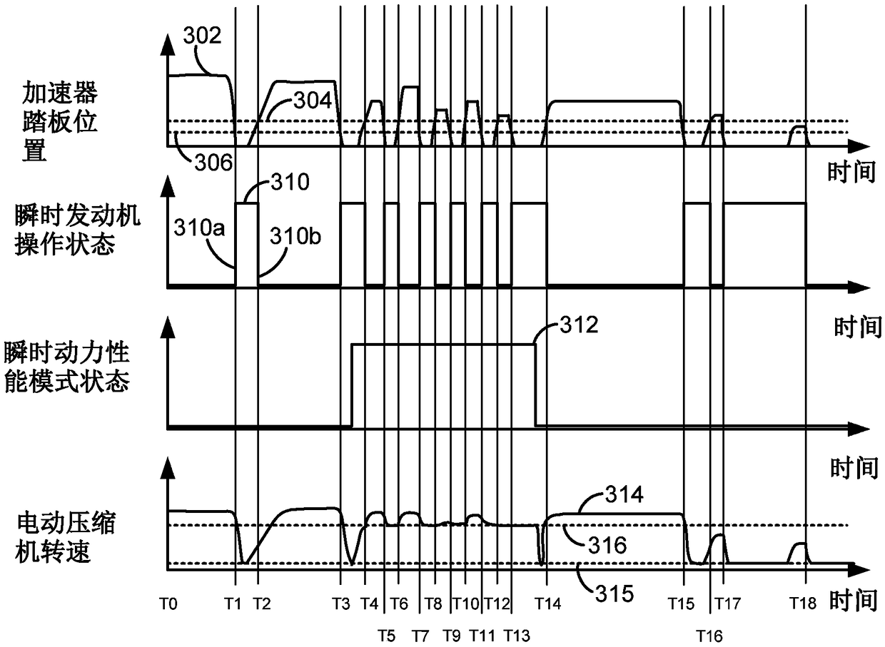
[0015] The invention relates to an electrically driven compressor controlling an engine and supplying air to the engine. Internal combustion engines can be figure 1 Configure as shown. like figure 2 As shown, the internal combustion engine may be included in a driveline or powertrain of a vehicle. The engine and electrically driven compressor can be based on image 3 and Figure 4 The sequence shown is performed. The internal combustion engine and the electrically driven compressor may be operated by a controller including means for performing Figure 5 and Image 6 The executable instructions for the method.

[0016] refer to figure 1 , including multiple cylinders ( figure 1 An internal combustion engine 10 of which one cylinder is shown) is controlled by an electronic engine controller 12 . Engine 10 is constructed of cylinder head 35 and cylinder block 33 including combustion chamber 30 and cylinder walls 32 . Piston 36 is positioned therein and reciprocates th...


PUM


Abstract

The application relates to a transient power control method for an engine that includes a compressor. Systems and methods for operating an engine that includes an electrically driven compressor are disclosed. In one example, a vehicle operating mode is determined and speed of an electrically driven compressor is adjusted responsive to the vehicle operating mode so that an engine may supply torquesooner in response to an increasing torque command.

Description

technical field [0001] The present invention relates to systems and methods for providing compensation for transient engine power requests or commands. The system and method may be applicable to an engine including a compressor for pressurizing air entering the engine. Background technique [0002] The engine may include a compressor to increase engine power. The compressor can be part of a turbocharger or a supercharger. At low engine loads, the compressor can spin at low engine speeds and provide little boost. As engine load increases, compressor speed may increase to provide increased boost to the engine. However, due to the inertia of the compressor, it may take longer than desired to bring the compressor up to speed to provide the desired level of boost. The delay period between commanding increased engine power and boost pressure reaching a value satisfying the increased engine power may be referred to as compressor lag. [0003] One way to reduce compressor lag f...

Claims


Application Information

Patent Timeline
Patent Type & Authority Applications(China)
IPC IPC(8): F02D41/00
CPCF02D41/0007F02D2200/1002F02D2200/602F02D2200/604F02D41/045F02D41/10F02B39/10F02D41/08Y02T10/12
Inventor J·E·罗林格T·凯利P·马修斯
Owner FORD GLOBAL TECH LLC
Learn More