
Compressor blade and compressor

A compressor and blade technology, applied in the field of gas turbines, can solve problems such as increasing friction loss and increasing blade surface area, and achieve the effects of reducing friction loss, reducing airflow separation, and reducing load

Inactive Publication Date: 2018-12-11
TSINGHUA UNIV
View PDF3 Cites 1 Cited by
  • Summary
  • Abstract
  • Description
  • Claims
  • Application Information

AI Technical Summary

Problems solved by technology

Although the curved blade can promote the low-energy fluid in the blade root and blade tip area to move to the middle fluid area, thereby reducing the low-energy fluid in the blade root and blade tip area, but the curved blade will significantly increase the surface area of ​​the blade, thereby increasing the friction loss

Method used


Image

  • Compressor blade and compressor
  • Compressor blade and compressor
  • Compressor blade and compressor

Examples


Embodiment 1

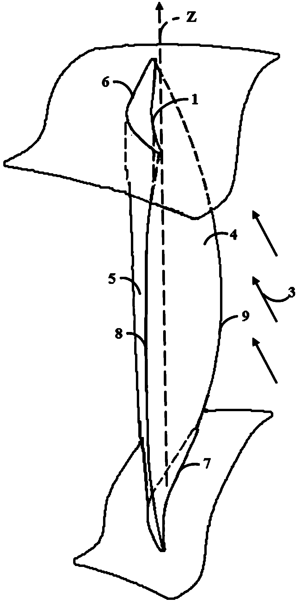
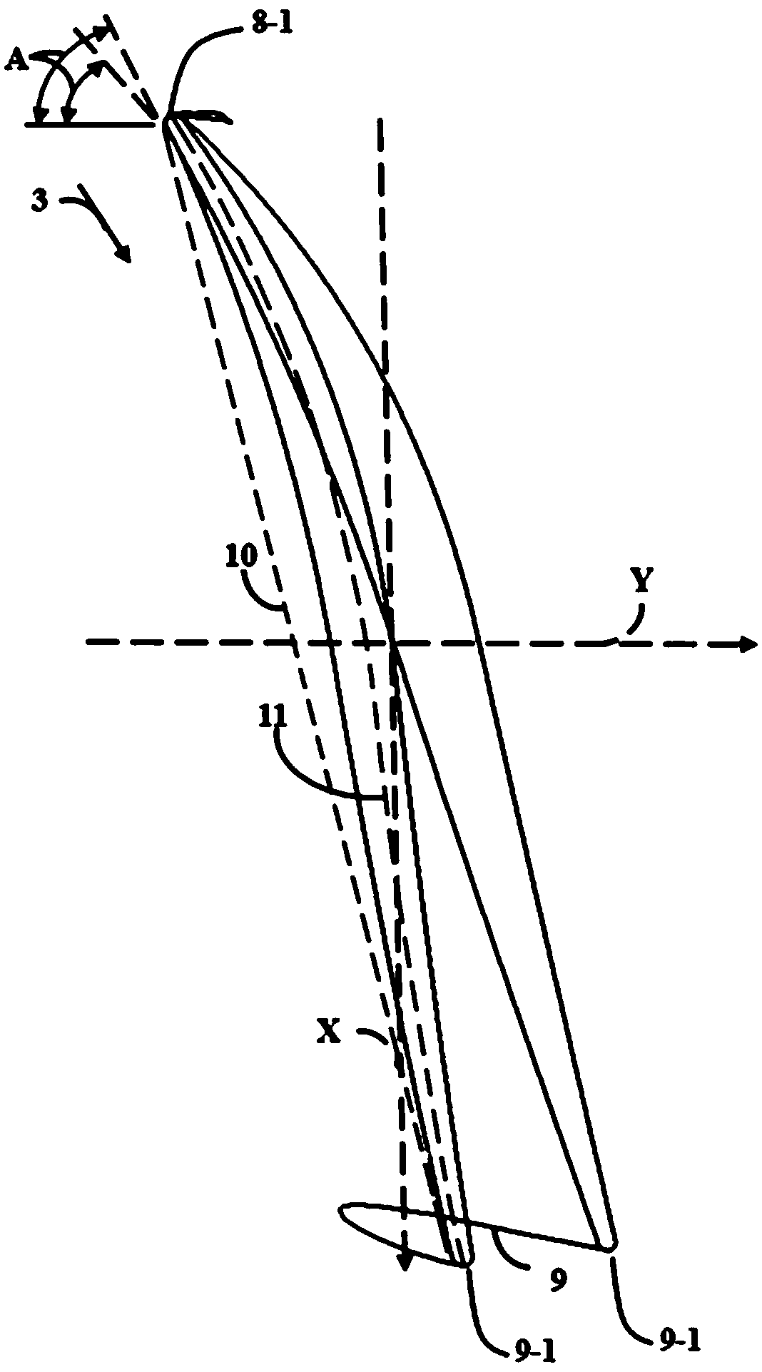
[0026] combine figure 1 and figure 2 As shown, the embodiment of the present invention provides a compressor blade. The compressor blade has a suction side 5 and a pressure side 4. The blade includes a blade root 6, a blade tip 7, and radial extended leaves;

[0027] The cross-sections of the blade top 7, blade center and blade root 6 are all parallel to the XY plane, wherein the X direction represents the axial direction, the Y direction represents the tangential direction, and the Z direction represents the radial direction; the trailing edge 9 of the blade root 6 and the trailing edge 9 of the blade tip 7 are twisted towards the suction side 5 respectively, and the trailing edge 9 of the blade is twisted towards the pressure side 4, so that the trailing edge point 9-1 on the cross-section of the blade tip 7 revolves around its leading edge point 8- 1 Rotate a specified angle along the direction where the suction side 5 is located, so that the trailing edge point 9-1 on t...

Embodiment 2

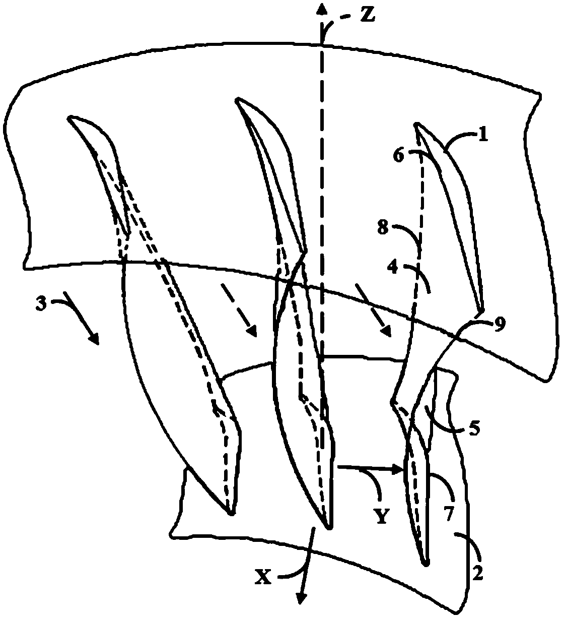
[0034] Such as image 3 As shown, the present invention also provides a compressor, which includes a hub 2 and a plurality of compressor blades 1 described above, and the plurality of compressor blades 1 are sequentially arranged at intervals along the circumference of the hub 2 . Since every two adjacent compressor blades 1 can surround and form an air 3 flow channel, when the compressor is running, the air 3 will be gradually compressed when it flows through the air 3 flow channel.

[0035] Preferably, the compressor blade 1 and the hub 2 are integrally formed. When manufacturing, it can be processed by milling, electrochemical and other methods. It should be noted that the compressor blade 1 can be integrally formed with the hub 2, and can also be detachably connected with the hub 2. For example, a dovetail can be arranged on the tip 7 of the compressor blade 1, and a dovetail can be provided on the side wall of the hub 2. Dovetails correspond one-to-one to dovetail slots...


PUM


Abstract

The invention relates to the field of gas turbines and provides a compressor blade and a compressor. The compressor blade comprises a blade tip, a blade root and a blade middle which axially extends from the blade root to the blade tip; the cross section of each of the blade root, the blade middle and the blade tip is parallel to XY planes, X-direction represents the axial direction, Y-direction represents the tangential direction, and the Z-direction represents the radial direction; the tailing edge of the blade tip and the tailing edge of the blade root respectively twist toward the suctionside, the tailing edge of the blade middle twists toward the pressure side, and the trailing edges on the cross sections of the blade root, the blade middle and the blade tip are sequentially arrangedaround the leading edge point in the direction of the suction side. The leading edge of the entire compressor blade remains unchanged assuredly, and airflow separation of the blade root and the bladetip can be reduced by allowing the tailing edges of the blade tip and the blade root to twist along the suction side respectively and the tailing edge of the blade middle to twist along the pressureside.

Description

technical field [0001] The invention relates to the field of gas turbines, in particular to a compressor blade and a compressor. Background technique [0002] Gas turbine is an important equipment to realize efficient and clean conversion of energy and ensure national energy security. A gas turbine is mainly composed of three parts: a compressor, a combustion chamber and a turbine. When the gas turbine is running, the air is first compressed by the compressor, and then the compressed air is guided to the combustion chamber, where it is fully mixed with fuel and burned to generate high-temperature flue gas, and finally the high-temperature flue gas is discharged into the turbine for expansion and work , to provide power for the compressor. [0003] At present, gas turbines are usually equipped with multi-stage axial flow compressors. Therefore, as one of the three major components of a gas turbine, the compressor plays a decisive role in the efficient operation of the entir...

Claims


Application Information

Patent Timeline
Patent Type & Authority Applications(China)
IPC IPC(8): F04D29/38
CPCF04D29/324
Inventor 李雪松任晓栋顾春伟丁傲霜
Owner TSINGHUA UNIV
Learn More