
Strong magnetic gathering type magnetofluid sealing structure

A magnetic fluid sealing and magnetic type technology, which is applied in the sealing of engines, engine components, mechanical equipment, etc., can solve problems such as poor magnetic gathering performance, and achieve the effects of enhanced pressure resistance, reduced magnetic resistance, and enhanced magnetic field strength

Inactive Publication Date: 2018-12-11
GUANGXI UNIVERSITY OF TECHNOLOGY
View PDF3 Cites 2 Cited by
  • Summary
  • Abstract
  • Description
  • Claims
  • Application Information

AI Technical Summary

Problems solved by technology

Most of the starting point is to consider increasing the magnetic field strength, but there is still room for further improvement of the existing magnetic fluid sealing performance, especially the poor magnetic gathering performance

Method used


Image

  • Strong magnetic gathering type magnetofluid sealing structure
  • Strong magnetic gathering type magnetofluid sealing structure
  • Strong magnetic gathering type magnetofluid sealing structure

Examples


Embodiment 1

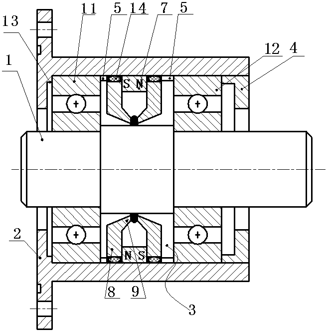
[0043] Such as figure 1 As shown, a magnetic fluid sealing structure of strong magnetic concentration type includes a hollow shell 2, one end of the shell 2 is closed, and the other end is open. A through hole is opened in the center of the closed end face of the housing 2 .

[0044] It also includes a shaft 1 penetrating from the through hole to the inner cavity of the housing 2 . In the space between the outer surface of the shaft 1 and the inner wall of the housing 2, two first pole pieces 3 are axially spaced apart. An axially magnetized permanent magnet ring 7 is interposed between the two first pole pieces 3 . The first pole piece 3 is annular. The outer circle of the axially magnetized permanent magnet ring 7 and the first pole shoe 3 abuts against the inner wall of the housing 2 . The outer circle of the first pole shoe 3 and the inner wall of the housing 2 are sealed by a sealing ring 14 .

[0045] Said first pole piece 3 comprises a ring body 8 . A first extens...

Embodiment 2

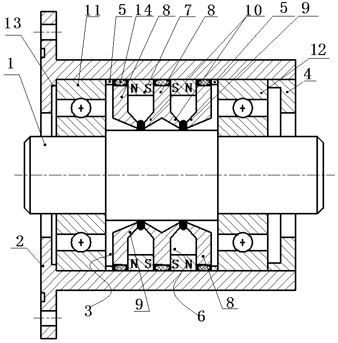
[0055] Such as figure 2 As shown, embodiment 1 is repeated, the difference is that two first pole pieces 3 and one second pole piece 6 are axially spaced in the space between the outer surface of the shaft 1 and the inner wall of the housing 2 . The two first pole pieces 3 have the same structure as that in Embodiment 1. The two first pole pieces 3 are respectively disposed near the closed end of the housing 2 and close to the open end of the housing 2 . The second pole piece 6 is arranged between the two first pole pieces 3 .

[0056] The second pole shoe 6 is ring-shaped and includes a ring body 8. On both end faces of the ring body 8, a second extension ring 10 is provided at the inner ring position of the ring body 8, and the second extension ring 10 has a minimum inner diameter greater than the outer diameter of shaft 1. The end surface of the second extension ring 10 is perpendicular to the axial direction of the shaft 1 . The difference between the minimum inner di...

Embodiment 3

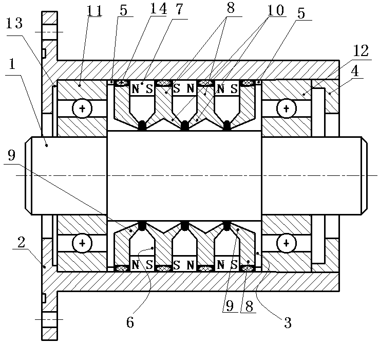
[0062] Such as image 3 As shown, embodiment 2 is repeated, the difference is that two first pole pieces 3 and at least two second pole pieces 6 are axially spaced in the space between the outer surface of the shaft 1 and the inner wall of the housing 2 .

[0063] The two first pole shoes 3 are respectively disposed near the closed end of the housing 2 and the open end of the housing 2 , and all the second pole shoes 6 are disposed between the two first pole shoes 3 .

[0064] In the second pole piece 6, the end faces of the two second extension rings 10 closest to the two first extension rings 9 are opposite to the end faces of the first extension rings 9 one by one, and there is a gap between the two opposite end faces. Filled with magnetic fluid.

[0065] The end faces of the second extension rings 10 of two adjacent second pole pieces 6 are opposite to each other, and there is a gap between the two opposite end faces, and the gap is filled with magnetic fluid.

[0066] ...


PUM


Abstract

The invention discloses a strong magnetic gathering type magnetofluid sealing structure. Two first pole shoes are arranged in a space between the outer surface of a shaft and the inner wall of a shellin the axial direction in a spaced manner, and an axial magnetization type permanent magnetic ring is sandwiched between the two first pole shoes; each first pole shoe is annular; the outer circle ofthe axial magnetization type permanent magnetic ring and the outer circle of each first pole shoe are connected with the inner wall of the shell in an abutting manner; each first pole shoe comprisesa ring body; the position, on an inner ring of each ring body, of the end face of one side of the ring body is provided with a first extending ring, and the minimum inner diameter of each first extending ring is larger than the outer diameter of the shaft; the two first pole shoes are arranged in the axis direction perpendicular to the shaft in a mirror symmetry manner; the two first extending rings are oppositely arranged, a gap is reserved between the opposite end surfaces, and magnetofluid is injected to the gap position; and the shaft is made from a non-magnetism-conductive material. Due to the strong magnetic gathering type magnetofluid sealing structure, the magnetic field does not pass through the shaft, the path of the whole magnetic loop becomes shorter, the corresponding magneticresistance is lowered, the magnetic field intensity in the whole magnetic path is greatly enhanced, the magnetism gathering purpose is achieved, and the sealing pressing resisting capacity of the magnetofluid is greatly enhanced.

Description

technical field [0001] The invention belongs to the field of mechanical engineering seals, and in particular relates to a strong magnetism-gathering magnetic fluid seal structure. Background technique [0002] The existing magnetic fluid sealing structure for the reciprocating movement of the shaft generally includes a housing with a hollow cavity, a shaft, a permanent magnet and a pole shoe are arranged between the shaft and the housing for magnetic fluid sealing, and the inner ring of the pole shoe is provided with pole teeth. [0003] There are generally two ways to improve the pressure resistance performance of magnetic fluid seals: first, try to increase the magnetic field strength; second, increase the saturation magnetization of magnetic fluid. Most of the starting point is to consider increasing the magnetic field strength, but there is still room for further improvement of the existing magnetic fluid sealing performance, especially the poor magnetic gathering perfor...

Claims


Application Information

Patent Timeline
Patent Type & Authority Applications(China)
IPC IPC(8): F16J15/43
CPCF16J15/43
Inventor 杨小龙陈帆何美丽
Owner GUANGXI UNIVERSITY OF TECHNOLOGY
Learn More