Overflow cut-off valve

A shut-off valve, over-current technology, applied in the direction of lift valve, valve details, safety valve, etc., can solve the problems of gas overflow poisoning or explosion, life safety threat, family property loss, etc., to ensure gas safety and small size , the effect of simple structure

Pending Publication Date: 2018-12-11
苏州福特曼机器人系统有限公司
View PDF0 Cites 0 Cited by
  • Summary
  • Abstract
  • Description
  • Claims
  • Application Information

AI Technical Summary

Problems solved by technology

[0002] As people pay more and more attention to environmental protection, gas is widely used in family life, and fire accidents caused by gas meter explosion due to gas overflow or sudden rise and overpressure of gas supply pressure occur from time to time, which not only destroys family property Huge losses have been suffered and people's lives have also been greatly threatened
In addition to irregular use, the lack of an automatic gas cut-off device on the existing gas supply pipeline is also an important reason for the gas fire accident, especially because of the poisoning or explosion caused by the gas overflow caused by the sudden increase in the flow rate of the gas supply pipeline. fire accident

Method used


Image

  • Overflow cut-off valve
  • Overflow cut-off valve
  • Overflow cut-off valve

Examples


Embodiment 1

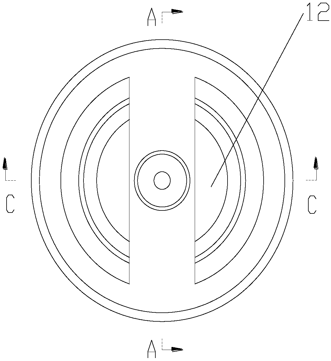
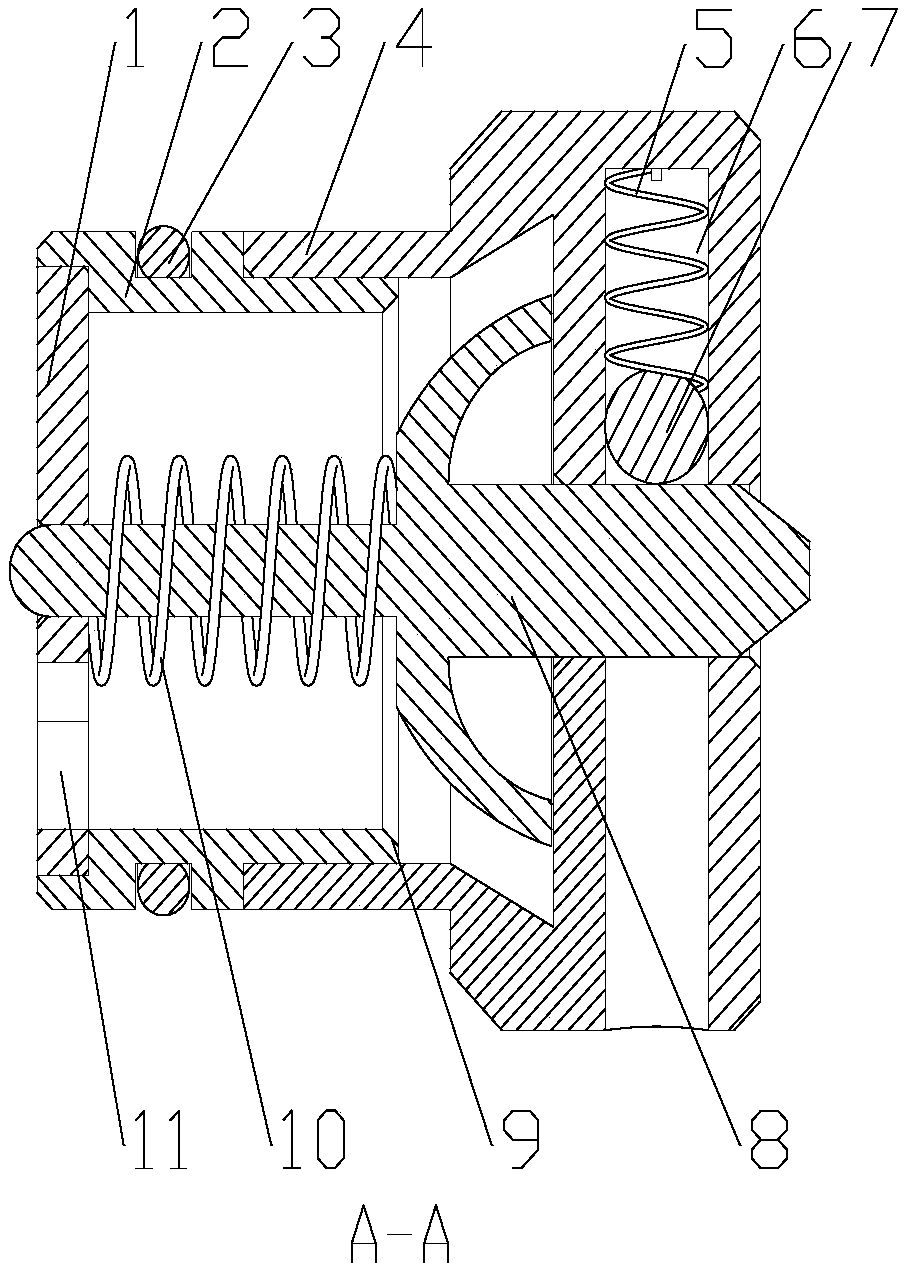
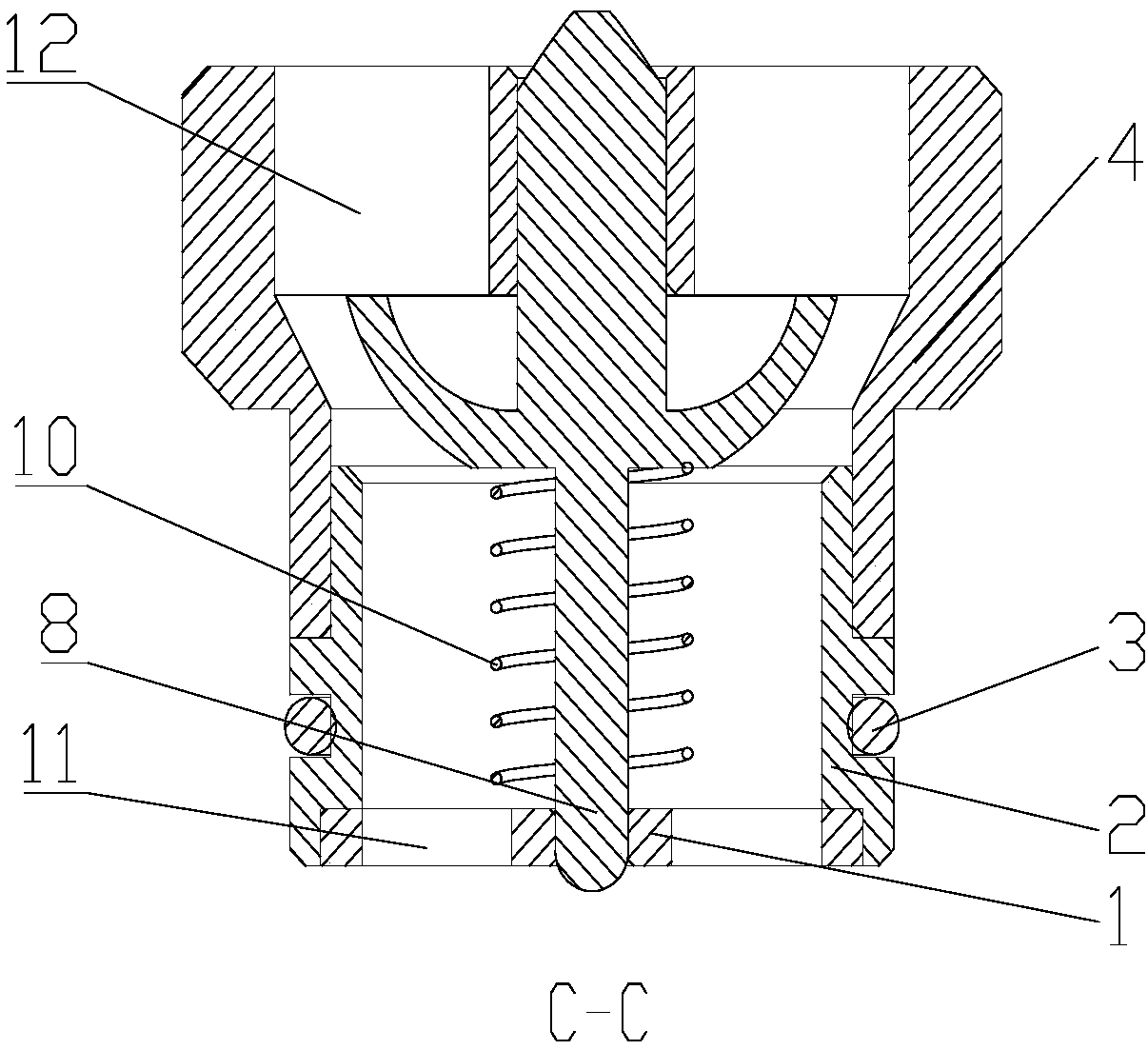
[0027] Such as figure 2 , image 3 and Figure 5 The overcurrent cut-off valve shown includes a valve body and a cut-off assembly, the cut-off assembly is installed in the valve body, and the valve body includes an air inlet flange 4 through which gas enters, and a retainer installed with an interference fit with the air inlet flange 4 Frame 2, an air outlet support frame 1 installed with an interference fit with the cage 2, the cut-off assembly includes a release spring 5, a steel ball 7, a valve core 8 and a return spring 10 that resets the valve core 8 after cutting off the gas, as Figure 6 As shown, the valve core 8 includes an upper guiding plug 81, a valve disc 83 and a lower guiding plug 82 connected in sequence. The valve core 8 has an integrated structure, and the structure is firmer and will not break. The valve disc The shape of 83 is hemispherical, and the opening faces the direction of the air inlet flange 4. The return spring 10 is sleeved on the guide lower ...

Embodiment 2

[0032] The working principle of this embodiment is the same as that of Embodiment 1, the difference is that: the valve disc 83 of the valve core 8 is in the shape of a sheet, the retainer 2 is threadedly connected with the air inlet flange 4, and the air outlet support frame 1 is connected with the retainer. Frame 2 threaded connection.

Embodiment 3

[0034] The working principle of this embodiment is the same as that of Embodiment 1, the difference is that: the retainer 2 and the air outlet support frame 1 adopt an integrated structure, and are connected to the air inlet flange 4 through threaded connection or interference fit.


PUM


Abstract

The invention discloses an overflow cut-off valve. The overflow cut-off valve comprises a valve body and a cut-off component and is characterized in that the valve body comprises a gas inlet flange, aretainer detachably connected with the gas inlet flange and a gas outlet support rack detachably connected with the retainer, the cut-off component is mounted in the valve body and comprises a release spring, a steel ball, a valve element and a reset spring, the valve element comprises a guide upper plug, a valve clack and a guide lower plug which are sequentially connected, the reset spring sleeves the guide lower plug, one end of the reset spring is abutted against the valve clack, the other end of the reset spring is abutted against the gas outlet support rack, one side, away from the retainer, of the gas inlet flange is provided with a spring hole for placing the release spring and the steel ball, the steel ball is arranged at one end, close to the valve element, of the release spring, and the release spring pushes the steel ball against the surface of guide upper plug. By the cut-off component, the cut-off valve can be automatically closed during overcurrent, the cut-off valve ismanually recovered when the flow is normal, and gas use safety is guaranteed.

Description

technical field [0001] The invention relates to a cutting device, in particular to an overcurrent cutting device. Background technique [0002] As people pay more and more attention to environmental protection, gas is widely used in family life, and fire accidents caused by gas meter explosion due to gas overflow or sudden rise and overpressure of gas supply pressure occur from time to time, which not only destroys family property Huge losses have been suffered and people's lives have also been greatly threatened. In addition to irregular use, the lack of an automatic gas cut-off device on the existing gas supply pipeline is also an important reason for the gas fire accident, especially because of the poisoning or explosion caused by the gas overflow caused by the sudden increase in the flow rate of the gas supply pipeline. caused fire accidents. Contents of the invention [0003] The technical problem to be solved by the invention is to provide a valve for automatic cut...

Claims


Application Information

Patent Timeline
Patent Type & Authority Applications(China)
IPC IPC(8): F16K17/30F16K1/36F16K27/02
CPCF16K17/30F16K1/36F16K27/02G05D7/0113G05D7/0133
Inventor 李向阳忻国君刘宋
Owner 苏州福特曼机器人系统有限公司
Why Eureka
Try Eureka