High-sensitivity fiber grating acceleration sensor

A technology of acceleration sensor and optical fiber grating, which is applied in speed/acceleration/shock measurement, acceleration measurement, instruments, etc., can solve problems such as difficulty in suppressing lateral acceleration sensitivity, inability to control the rotation amount of L-shaped lever, and low sensitivity of acceleration sensor, etc., to achieve The effect of suppressing lateral sensitivity, simple structure, and small dynamic error

Pending Publication Date: 2018-12-11
SHIJIAZHUANG TIEDAO UNIV
View PDF10 Cites 10 Cited by
  • Summary
  • Abstract
  • Description
  • Claims
  • Application Information

AI Technical Summary

Problems solved by technology

Due to the characteristics of its structure, fiber gratings are basically pasted (or suspended) directly on the beam structure, and the beam is used as an elastic element. The grating changes with the deformation of the beam. This type of structure leads to low sensitivity of the acceleration sensor. Prone to chirp, and difficult to suppress its lateral acceleration sensitivity
Zhang Wentao and others disclosed a temperature-insensitive fiber grating acceleration sensor (CN101285847B). Although the sensitivity of the sensor has been improved, the rotation amount of the L-shaped lever cannot be controlled. Not only is it easily damaged when vibrating violently, but also the dynamic error is large.
People such as Jiang Shaodong disclose a kind of fiber grating acceleration sensor (CN107478860A), although this structure increases to some extent the sensitivity of sensor, but does not avoid the shortcoming of low sensitivity of traditional cantilever beam structure, the effect of sensitivity increase is limited

Method used


Image

  • High-sensitivity fiber grating acceleration sensor
  • High-sensitivity fiber grating acceleration sensor
  • High-sensitivity fiber grating acceleration sensor

Examples


Embodiment Construction

[0027] In order to make the technical problems, technical solutions and beneficial effects to be solved by the present invention clearer, the present invention will be further described in detail below in conjunction with the accompanying drawings and embodiments. It should be understood that the specific embodiments described here are only used to explain the present invention, not to limit the present invention.

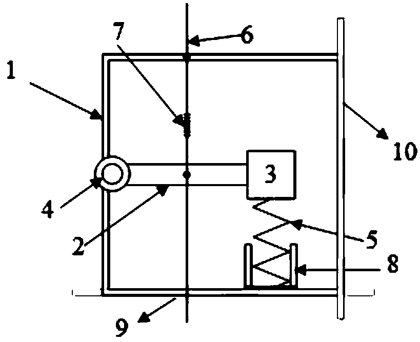
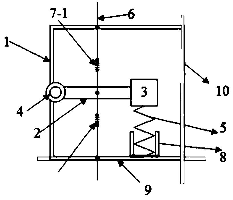
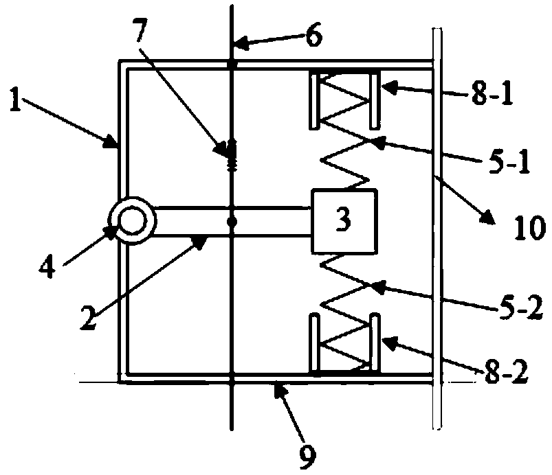
[0028] see Figure 1 to Figure 4 It is a specific embodiment of a high-sensitivity fiber grating acceleration sensor of the present invention, including a frame body 1, a fiber grating 7 and a mass block 3, and is characterized in that it also includes a measurement substrate A 9 or a measurement substrate B10, a rigid beam 2 and Balance spring 5, the equilibrium position of the rigid beam 2 is substantially parallel to the measurement substrate A 9 or substantially perpendicular to the measurement substrate B 10, and one end of the rigid beam 2 is fixed to the mea...


PUM


Abstract

The invention provides a high-sensitivity fiber grating acceleration sensor, which belongs to the technical field of vibration monitoring. The high-sensitivity fiber grating acceleration sensor comprises a measurement substrate A or a measurement substrate B, a rigid beam and a balance spring, wherein the balance position of the rigid beam is basically parallel with the measurement substrate A orbasically vertical to the measurement substrate B; one end of the rigid beam is hinged with a frame body fixedly connected with the measurement substrate A or the measurement substrate B through a rotating shaft, and the other end of the rigid beam is fixed with a mass block; one side of the rigid beam or the mass block is provided with the balance spring for enabling the rigid beam to be in a balance position; one side or two sides of the rigid beam is or re provided with one or two fiber gratings; and when the measurement substrate A or the measurement substrate B vibrates along with a monitored piece, the fiber grating can directly sense the vibration information of the rigid beam. The sensor sensitivity is improved obviously, the transverse sensitivity of the acceleration sensor can beeffectively suppressed, and the high-sensitivity fiber grating acceleration sensor has the advantages of simple structure, durability, not easy damage, small dynamic errors, accurate measurement, high sensitivity, high accuracy and high efficiency.

Description

technical field [0001] The invention belongs to the technical field of vibration monitoring, and more specifically relates to a high-sensitivity fiber grating acceleration sensor. Background technique [0002] Constructions such as civil engineering structures, machine tools, automobiles, spacecraft, etc. are subject to time-varying loads, i.e. they are all subject to various dynamic loads and therefore they vibrate to varying degrees. Long-term vibration will cause them to generate cracks and crack growth, and finally lead to fatigue damage of components. Severe vibration will also affect the reliability, stability and precision of the structure (equipment) operation. When a structure is damaged or destroyed, its mode shape will change. Therefore, the damage of the structure can be understood by monitoring the vibration parameters of the structure. Therefore, vibration monitoring has become very common and especially important, and vibration monitoring relies on accelerat...

Claims


Application Information

Patent Timeline
Patent Type & Authority Applications(China)
IPC IPC(8): G01P15/093G01H9/00
CPCG01H9/006G01P15/093
Inventor 李剑芝赵德胜许红彬孙宝臣杜彦良赵维刚王莽
Owner SHIJIAZHUANG TIEDAO UNIV
Why Eureka
Try Eureka