Supercharge Your Innovation With Domain-Expert AI Agents!

Signal reception channel calibration method and magnetic resonance calibration system

A signal receiving and calibrating system technology, which is applied in the field of medical imaging, can solve the problems that the actual gain and phase of the signal are not the same, and affect the image quality of magnetic resonance images, so as to improve the accuracy, reduce the cost and ensure the same effect

Active Publication Date: 2018-12-11
SHANGHAI NEUSOFT MEDICAL TECH LTD
View PDF14 Cites 4 Cited by
  • Summary
  • Abstract
  • Description
  • Claims
  • Application Information

AI Technical Summary

Problems solved by technology

However, due to the dispersion of electronic components and differences in manufacturing processes, even if the design principles and hardware structures of each signal receiving channel are exactly the same, in practical applications, when the same signal is received through each signal receiving channel, the received signal The actual gain and phase of the MRI are also usually different, which greatly affects the image quality of the final MRI image

Method used


Image

  • Signal reception channel calibration method and magnetic resonance calibration system
  • Signal reception channel calibration method and magnetic resonance calibration system
  • Signal reception channel calibration method and magnetic resonance calibration system

Examples


Embodiment Construction

[0019] Reference will now be made in detail to the exemplary embodiments, examples of which are illustrated in the accompanying drawings. When the following description refers to the accompanying drawings, the same numerals in different drawings refer to the same or similar elements unless otherwise indicated. The implementations described in the following exemplary embodiments do not represent all implementations consistent with this application. Rather, they are merely examples of apparatuses and methods consistent with aspects of the present application as recited in the appended claims.

[0020] The terminology used in this application is for the purpose of describing particular embodiments only, and is not intended to limit the application. As used in this application and the appended claims, the singular forms "a", "the", and "the" are intended to include the plural forms as well, unless the context clearly dictates otherwise. It should also be understood that the term...


PUM


Abstract

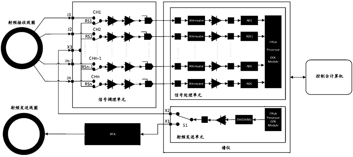
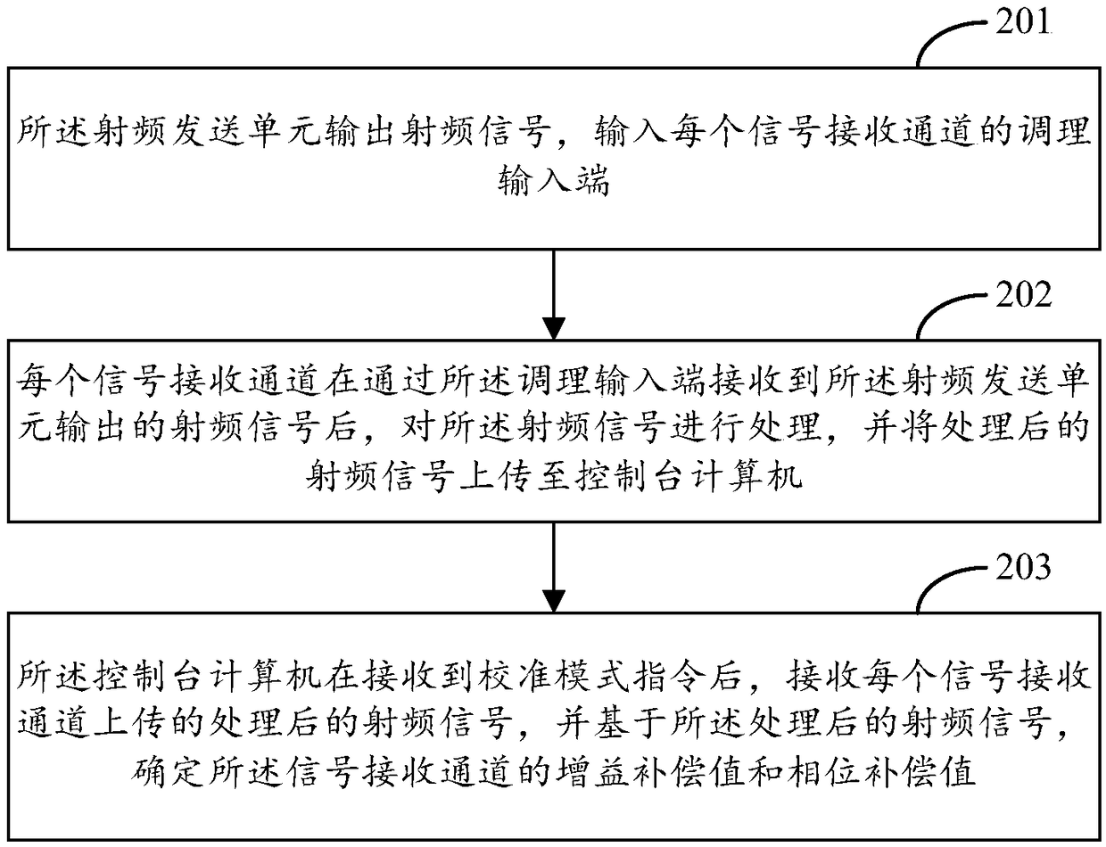
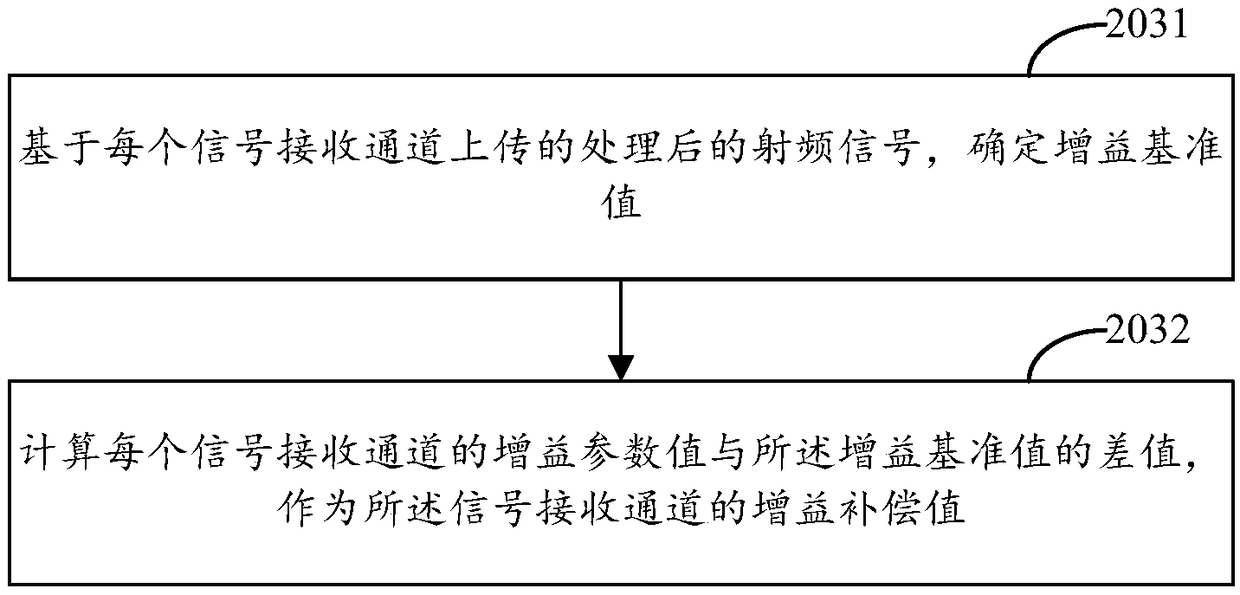
The invention provides a signal reception channel calibration method and a magnetic resonance calibration system. The magnetic resonance calibration system comprises an RF sending unit, signal reception channels with the same hardware structures and a console computer. The method comprises that the RF sending unit outputs an RF signal, and the RF signal is input to the conditioning input end of each signal reception channel; after receiving the RF signal from the RF sending unit, each signal reception channel processes the RF signal, and uploads the processed RF signal to the console computer;and after receiving a calibration mode instruction, the console computer receives the processed RF signal from each signal reception channel, and determines a gain compensation value and a phase compensation value of the signal reception channel on the basis of the processed RF signal and the RF signal output by the RF sending unit. The calibration accuracy of the signal reception channels can beimproved, and thus, the quality of a finally obtained magnetic resonance image is improved.

Description

technical field [0001] The present application relates to the technical field of medical imaging, in particular to a signal receiving channel calibration method and a magnetic resonance calibration system. Background technique [0002] Magnetic Resonance Imaging (MRI) is one of the main imaging methods in modern medical imaging. Its basic working principle is to use the magnetic resonance phenomenon to excite hydrogen protons in the human body with radio frequency pulses, and to use gradient fields for position encoding. , and then the receiving coil is used to receive the magnetic resonance signal with position information, and finally the magnetic resonance image is reconstructed by Fourier transform. [0003] The raw magnetic resonance signal received by the receiving coil is usually within -24dBm ~ -36dBm, which does not match the dynamic range of the digital-to-analog converter used in the magnetic resonance imaging system. Therefore, it is necessary to amplify, filter...

Claims


Application Information

Patent Timeline
Patent Type & Authority Applications(China)
IPC IPC(8): G01R33/58A61B5/055
CPCA61B5/055G01R33/583
Inventor 王艳史建华孙容吴林
Owner SHANGHAI NEUSOFT MEDICAL TECH LTD
Features
  • R&D
  • Intellectual Property
  • Life Sciences
  • Materials
  • Tech Scout
  • Unparalleled Data Quality
  • Higher Quality Content
  • 60% Fewer Hallucinations
Learn More