Transflective film and an aerial display device

A display device, transflective technology, applied in the directions of optical elements, optics, instruments, etc., can solve the problems of large display equipment, simple graphics, poor display effect, etc., and achieve good imaging effect, simple structure, and easy to achieve effects.

Active Publication Date: 2018-12-11
BOE TECH GRP CO LTD
View PDF11 Cites 13 Cited by
  • Summary
  • Abstract
  • Description
  • Claims
  • Application Information

AI Technical Summary

Problems solved by technology

[0004] In order to solve the above-mentioned technical problems, the embodiment of the present invention provides a semi-permeable and semi-reflective diaphragm and an aerial display device, which solves the problem that in the existing aerial imaging techno

Method used


Image

  • Transflective film and an aerial display device
  • Transflective film and an aerial display device
  • Transflective film and an aerial display device

Examples


Embodiment Construction

[0057] In order to make the purpose, technical solution and advantages of the present invention more clear, the embodiments of the present invention will be described in detail below in conjunction with the accompanying drawings. It should be noted that, in the case of no conflict, the embodiments in the present application and the features in the embodiments can be combined arbitrarily with each other.

[0058] The steps shown in the flowcharts of the figures may be performed in a computer system, such as a set of computer-executable instructions. Also, although a logical order is shown in the flowcharts, in some cases the steps shown or described may be performed in an order different from that shown or described herein.

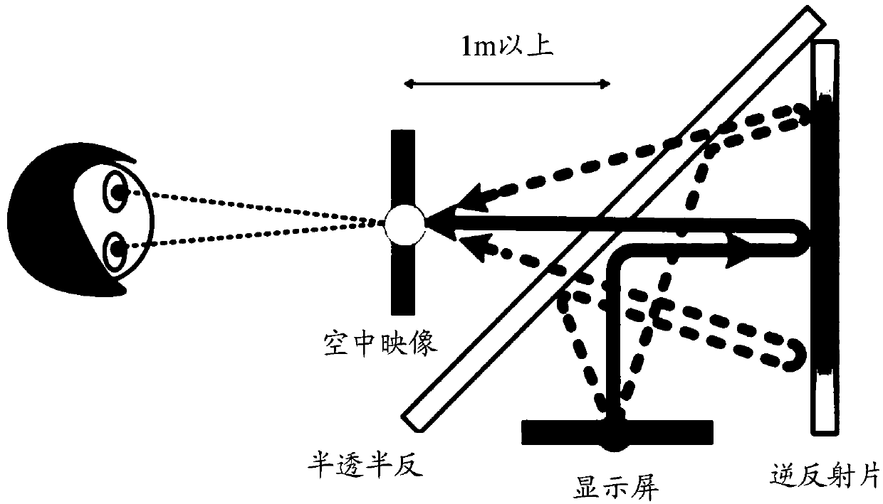
[0059] Several common aerial imaging technologies and their corresponding shortcomings have been described in the above background technology. In recent years, some new aerial display technologies have also been developed, such as figure 1 As shown, it is...


PUM


Abstract

The embodiment of the present invention discloses a transflective film and an aerial display device. The aerial display device comprises: a first polarizing device and a second polarizing device disposed on a box; and a transflective structure and a transflective film disposed between the first polarizing device and the second polarizing device. The aerial display device is provided with a first quarter-wavelength plate at a side close to the first polarizing device. A second quarter-wavelength plate is disposed between the transflective structure and the transflective film. According to the aerial display device, the polarized light passing through the first polarizing device is processed by an optical path inside the aerial display device such that the polarized light passing through thesecond polarizing device forms an aerial image. The embodiment of the present invention solves the problems in the existing aerial imaging technology that a display device is large in size, complicated in structure, simple in displayed images, and poor in display effect, and has difficulty in displaying three-dimensional images.

Description

technical field [0001] This application relates to but not limited to the technical field of in-air display, especially a semi-permeable and semi-reflective membrane and an in-air display device. Background technique [0002] Aerial imaging technology refers to the direct display of two-dimensional or three-dimensional images in the air without a medium, so that people or objects can directly "pass through" the screen, so as to achieve a good interactive and immersive display effect. [0003] At present, the relatively mature aerial display products on the market are mostly applied by projection technology, such as: aerosol projection display, holographic projection display and laser projection display. Among them, the aerosol projection display is to project the ordinary projection screen on the aerosol, the display screen is flat, and the image quality is extremely unstable; the holographic projection display is to divide the light emitted by the bottom light source into t...

Claims


Application Information

Patent Timeline
IPC IPC(8): G02B5/00G02B27/26G02B30/25
CPCG02B5/00G02B30/25G02B5/124G02B30/60G02B27/283G02B5/3066G02B5/128G02B30/56
Inventor 李小龙秦纬彭宽军高雪岭张方振彭锦涛王锦谦杨苗苗孙双张春芳李胜男
Owner BOE TECH GRP CO LTD
Why Eureka
Try Eureka