Smart home remote control system
A remote control system and intelligent technology, applied in the general control system, control/adjustment system, program control, etc., can solve problems such as difficult application, poor real-time performance, and high equipment cost
- Summary
- Abstract
- Description
- Claims
- Application Information
AI Technical Summary
Problems solved by technology
Method used
Image
Examples
Embodiment Construction
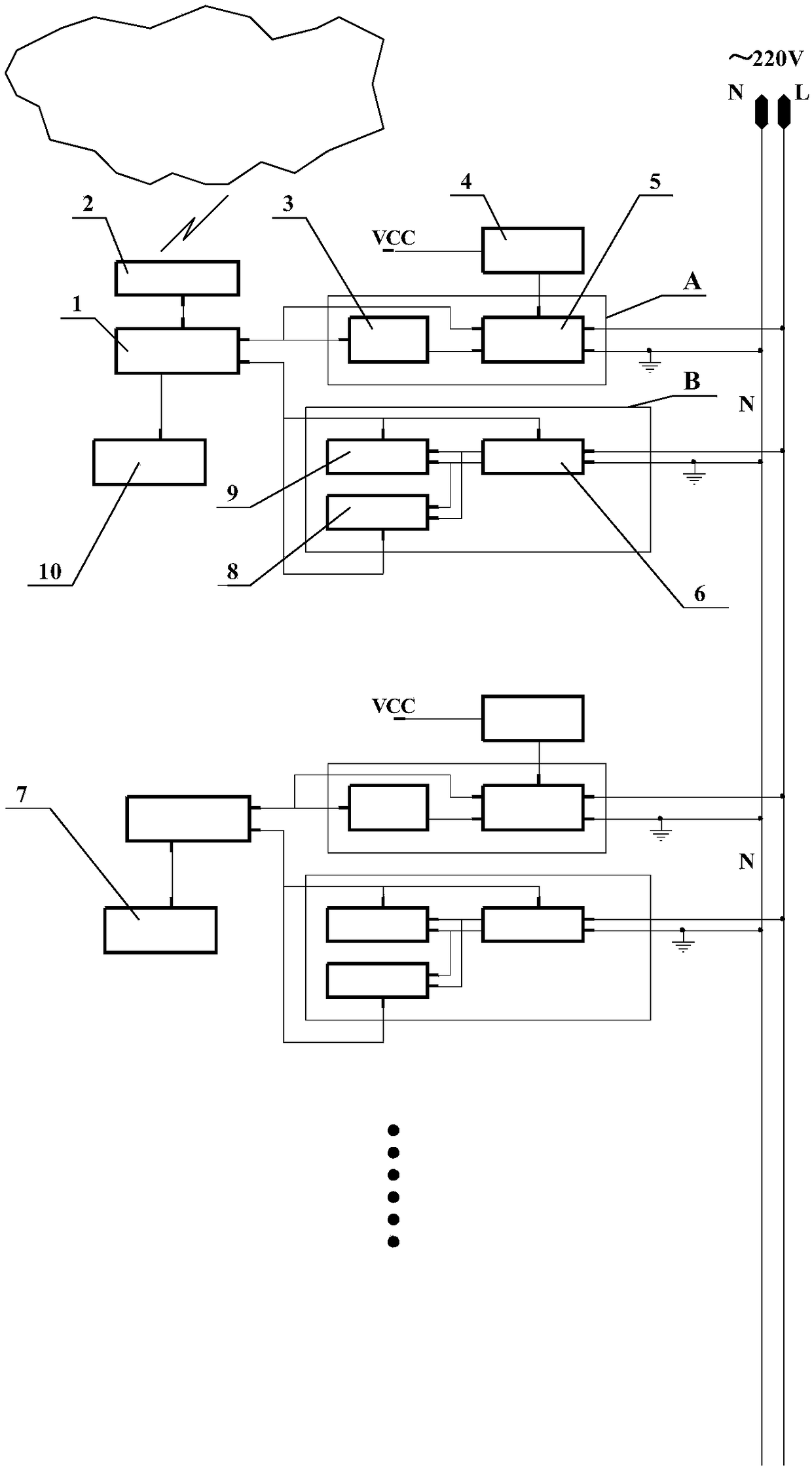
[0052] The circuit structure block diagram of a smart home remote control system is as follows: figure 2 shown. It consists of a main controller and multiple electrical controllers. The main controller is composed of a signal sending terminal A, a signal receiving terminal B, a 4G wireless router 2 , a keyboard display module 10 and a microcontroller module 1 . The electrical appliance controller is composed of a signal transmitting terminal A, a signal receiving terminal B, an electrical appliance switch module 7 and a microcontroller module 1, and the main controller communicates with the electrical appliance controller through the power line. The computer server is the computer management system located on the top layer, which is composed of 4G wireless router, microcontroller module and computer.
[0053] The hardware structure of the signal sending end A, the signal receiving end B of the power line communication in the main controller and the electrical appliance cont...
PUM
 Abstract
Description
Claims
Application Information
 - R&D
- Intellectual Property
- Life Sciences
- Materials
- Tech Scout
- Unparalleled Data Quality
- Higher Quality Content
- 60% Fewer Hallucinations
Browse by: Latest US Patents, China's latest patents, Technical Efficacy Thesaurus, Application Domain, Technology Topic, Popular Technical Reports.
© 2025 PatSnap. All rights reserved.Legal|Privacy policy|Modern Slavery Act Transparency Statement|Sitemap|About US| Contact US: help@patsnap.com


