A tool axis vector optimization method and system based on multi-objective constraints

A tool axis vector and optimization method technology, which is applied in the field of tool axis vector optimization methods and systems based on multi-objective constraints, can solve the problem of overcutting or collision between the tool and the workpiece, cannot guarantee the stability of the tool axis vector, and cannot meet the Processing needs and other issues, to achieve the effect of providing processing quality and efficiency, improving CNC processing quality, and ensuring stability

Active Publication Date: 2019-11-12
HUAZHONG UNIV OF SCI & TECH
View PDF13 Cites 0 Cited by
  • Summary
  • Abstract
  • Description
  • Claims
  • Application Information

AI Technical Summary

Problems solved by technology

[0003] At present, in the optimization process of the tool axis vector, many algorithms have corrected the overcut or collision of the tool, but cannot guarantee that the motion trajectory of the tool axis vector is smooth
For example, the patent CN201310451890.3 discloses a kinematically constrained five-axis CNC machining tool vector stabilization method for complex curved surfaces, which ensures the smooth movement of the machine tool rotation axis, but does not consider the overcut or collision between the tool and the workpiece during the machining process , and the calculation of the tool axis vector is not a systematic and comprehensive solution method, which cannot meet a wide range of processing needs; patent CN201710748234.8 discloses a tool axis vector optimization method based on covariant field functionals, which provides a unified framework The tool axis vector optimization method ensures the stability of the tool axis vector and avoids the tool from overcutting or colliding during the machining process. However, the discrete method of the discrete mathematical model obtained by this method cannot guarantee good tool axis vector stability. On the issue of overcut prevention, there is no reasonable way to specify the rake angle range

Method used


Image

  • A tool axis vector optimization method and system based on multi-objective constraints
  • A tool axis vector optimization method and system based on multi-objective constraints
  • A tool axis vector optimization method and system based on multi-objective constraints

Examples


Embodiment Construction

[0052] In order to make the objectives, technical solutions and advantages of the present invention clearer, the following further describes the present invention in detail with reference to the accompanying drawings and embodiments. It should be understood that the specific embodiments described herein are only used to explain the present invention, but not to limit the present invention. In addition, the technical features involved in the various embodiments of the present invention described below can be combined with each other as long as they do not conflict with each other.

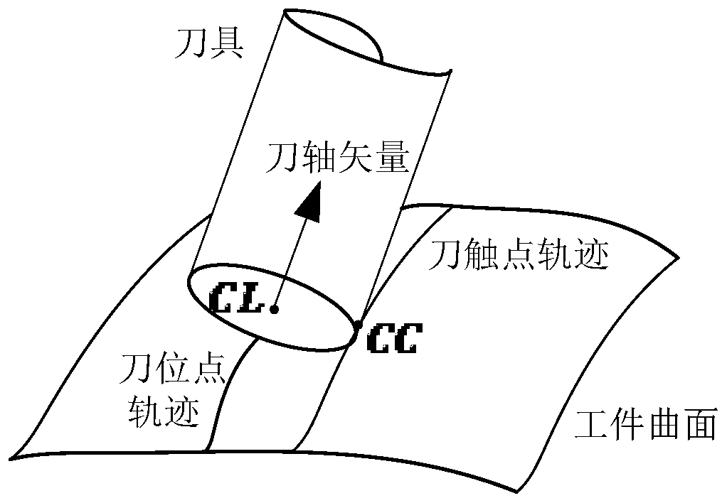
[0053] figure 1 It is a schematic diagram of the structure of the tool axis vector in actual machining in the numerical control machining constructed according to the preferred embodiment of the present invention, such as figure 1 As shown, the tool contact point, referred to as CC point, refers to the point where the workpiece surface and the tool surface are tangent when the tool is milling the surf...


PUM


Abstract

The invention belongs to the field of milling processing, and particularly discloses a cutter-axis vector optimization method based on multi-objective constraints and system. The method comprises steps: S1, a multi-objective constrained cutter-axis vector optimization model is built according to cutter axis optimization requirements; S2, discretization is carried out on the cutter-axis vector optimization model to obtain a discrete cutter-axis vector optimization model; S3, the discrete cutter-axis vector optimization model is converted to a cutter-axis vector optimization model with a variables in a local coordinate system as an optimization variable; and S4, a cutter-axis feasible region without over cutting in the cutter-axis vector optimization model is calculated, and the optimized cutter-axis vector is solved. The cutter-axis vector and the processing path can be ensured to be more stable, the cutter can be prevented from generating over cutting or collision during a processing process, the method and the system are applicable to workpiece surfaces with different parameterization, the processing precision is high, and the surface quality of a processing working piece is good.

Description

Technical field [0001] The invention belongs to the field of milling processing, and more specifically, relates to a method and system for optimizing a tool axis vector based on multi-objective constraints. Background technique [0002] In multi-axis CNC machining, the sharp change of the tool axis vector will cause overcutting and collision between the tool and the workpiece surface, so that there are often sawtooth shapes in the tool path, and vibration in actual machining, which affects the machining accuracy and surface quality. . Therefore, the rate of change of the tool axis vector must be limited, while avoiding tool collision and overcutting. [0003] At present, in the process of optimizing the tool axis vector, many algorithms have corrected the overcut or collision of the tool, but it cannot guarantee that the motion trajectory of the tool axis vector is smooth. For example, patent CN201310451890.3 discloses a kinematically constrained five-axis CNC machining tool vect...

Claims


Application Information

Patent Timeline
Patent Type & Authority Patents(China)
IPC IPC(8): G05B19/19
CPCG05B19/19G05B2219/35349
Inventor 李振瀚张玉明杨方召黄璐璐陈吉红
Owner HUAZHONG UNIV OF SCI & TECH
Why Eureka
Try Eureka