Heat power plant heating network monitoring system

A technology of monitoring system and thermal power plant, applied in the field of power system, can solve the problems of the stability and reliability of the automatic control system and the weak and lack of anti-interference design, and can not effectively solve the problems of hydraulic balance and thermal balance of the pipe network

Inactive Publication Date: 2018-12-11
JINING POLYTECHNIC
View PDF4 Cites 5 Cited by
  • Summary
  • Abstract
  • Description
  • Claims
  • Application Information

AI Technical Summary

Problems solved by technology

The functions of these systems in terms of energy monitoring, statistics, and energy forecasting are often lacking, and cannot effectively solve the hydraulic balance and thermal balance of the pipeline network.
Lack of energy consumption data analysis

Method used


Image

  • Heat power plant heating network monitoring system

Examples


Embodiment Construction

[0027] The present invention will be described in detail below in combination with specific embodiments.

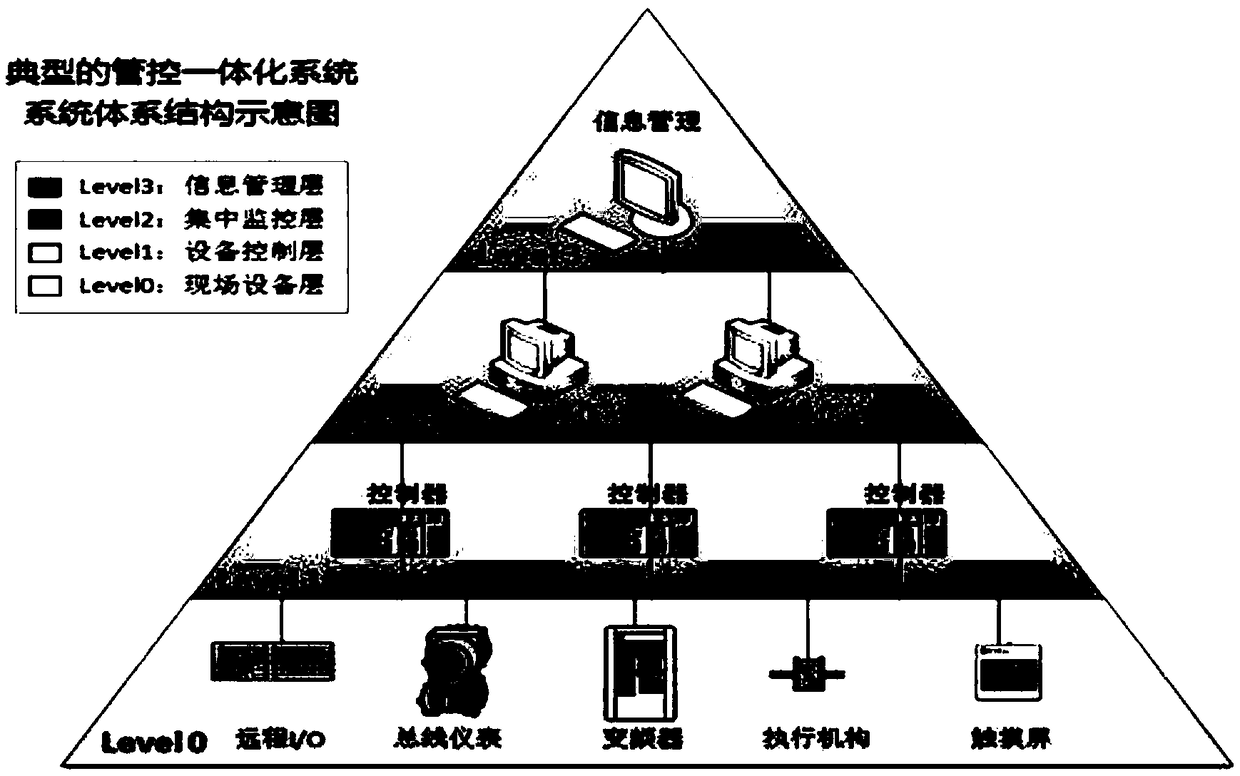
[0028] The system such as figure 1 As shown, it consists of field device layer, centralized monitoring layer, information management layer and network connecting each layer.

[0029] 1. Field device layer

[0030] The field equipment layer is composed of measuring instruments, actuators, remote I / O, PLC and other control systems, control network and liquid crystal display operation terminals arranged on site. The liquid crystal display mainly completes the display of various monitoring screens and acquisition parameters, and realizes the input of some parameter setting information. The main functions of the field equipment layer: First, realize the integration of the control systems of each thermal station, including the operation status of the equipment (such as the operation status of the water pump, valve position, etc.), the operating parameters of the thermal stati...


PUM


Abstract

The invention discloses a heat power plant heating network monitoring system, which comprises a field device layer, a centralized monitoring later, an information management layer and a network for connecting the layers. The heat power plant heating network monitoring system has the beneficial effects that integration of management and control for the heating network is realized. energy managementand control for the heating system are combined, centralized and dynamic balance control on the heating network is realized, hydraulic balance and thermodynamic balance for a primary network can be effectively solved, and optimal control and decision support for energy conservation and consumption reduction can be realized.

Description

technical field [0001] The invention belongs to the technical field of electric power systems, and relates to a monitoring system for a heating network of a thermal power plant. Background technique [0002] Centralized heating is generally used for heating in winter in northern my country. Thermal power plants send hot water to heat exchange stations in residential quarters and enterprises through urban high-temperature heating pipelines. In the heat exchange station, the hot water in the high-temperature pipeline and the hot water in the secondary network exchange heat through the heat exchanger. After heat exchange, the hot water in the secondary network flows into each living room. In the above process, the heat supply dispatching department needs to conduct centralized real-time monitoring of parameters such as heat, temperature, pressure, flow, liquid level and other parameters in the first station and heat exchange station scattered in different geographical locatio...

Claims


Application Information

Patent Timeline
IPC IPC(8): G05B19/418G01D21/02
CPCG01D21/02G05B19/41865Y02P90/02
Inventor 王友权张西忠张兴军孟凡文黄福军
Owner JINING POLYTECHNIC
Why Eureka
Try Eureka