A reaction chamber cavity based on an aerodynamic configuration of a plasma etcher

A plasma etching and pneumatic layout technology, applied in the field of reaction chamber cavity, can solve problems such as inconvenience of use, achieve the effects of smooth exchange, easy installation and maintenance, stable and uniform response

Inactive Publication Date: 2018-12-11
珠海安普特科技有限公司
View PDF2 Cites 3 Cited by
  • Summary
  • Abstract
  • Description
  • Claims
  • Application Information

AI Technical Summary

Problems solved by technology

[0004] The object of the present invention is to provide a reaction chamber cavity based on the pneumatic layo...

Method used


Image

  • A reaction chamber cavity based on an aerodynamic configuration of a plasma etcher
  • A reaction chamber cavity based on an aerodynamic configuration of a plasma etcher
  • A reaction chamber cavity based on an aerodynamic configuration of a plasma etcher

Examples


Embodiment Construction

[0017] The following will clearly and completely describe the technical solutions in the embodiments of the present invention with reference to the accompanying drawings in the embodiments of the present invention. Obviously, the described embodiments are only some, not all, embodiments of the present invention. Based on the embodiments of the present invention, all other embodiments obtained by persons of ordinary skill in the art without making creative efforts belong to the protection scope of the present invention.

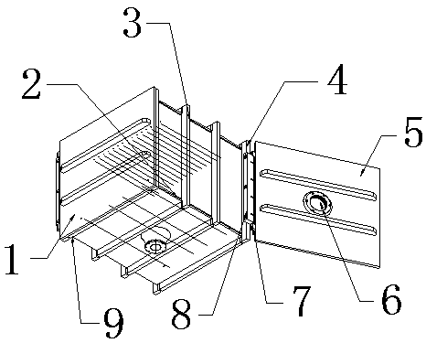
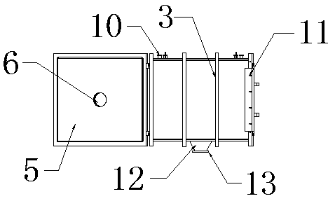
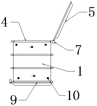
[0018] see Figure 1-5 , the present invention provides a reaction chamber cavity based on the aerodynamic layout of a plasma etching machine, including a cavity 1, a mounting seat 2 and a cavity door 5, and a first door frame 4 and a second door frame 9 are respectively provided at both ends of the cavity 1 , one side of the first door frame 4 and one side of the second door frame 9 are respectively provided with a first mounting plate 8 and a second mounting...


PUM


Abstract

The invention discloses a reaction chamber cavity based on the pneumatic configuration of a plasma etching machine. The cavityinclude a cavity, a mounting baseand a chamber door, A first mounting plate and a second mounting plate are respectively arranged at one end of both sides of the cavity, the two ends of the second mounting plate and the two ends of the first mounting plate are respectivelyrotatably connected with the two sides of one end of the cavity door through rotary joints, both chambers have viewing windows in the middle, according to the invention, the processing gas of the device is diverted once through the cloth pipe, uniformly distribute in the lower groove and the two sides of the product, the by-product of the reaction product and the non-ionized gas are diverted for the second time through the side plate of the rectangular box on the bottom surface of the cavity, and then are diverted for the third time through the diameter-changing pipe on the outside of the bottom surface of the cavity. The aerodynamic configuration can effectively ensure that the process gas is uniformly distributed in each tank and on both sides of the processed product, so that the gas flow and ions in the reaction chamber are stably exchanged, and the reaction is stable, uniform and free of plain flow.

Description

technical field [0001] The invention relates to a reaction chamber cavity, in particular to a reaction chamber cavity based on the pneumatic layout of a plasma etching machine, and belongs to the technical field of etching machines. Background technique [0002] Etching is usually also called photochemical etching, which refers to removing the protective film of the area to be etched after developing, and contacting chemical solution during etching to achieve the effect of dissolution and corrosion. At present, most of the etching machines on the market are spray etching machines. The type etching machine is equipped with an etching spray device, and the top of the fuselage is a plane structure, and the front and back sides of the workpiece are etched by the spray device. [0003] When the traditional device is in use, there will be gas turbulence inside the device, which is not conducive to the normal use of the device; at the same time, when the traditional device is insta...

Claims


Application Information

Patent Timeline
IPC IPC(8): H01J37/32
Inventor 廖鑫王奇
Owner 珠海安普特科技有限公司
Why Eureka
Try Eureka