
A millimeter wave wireless terminal device

A wireless terminal, millimeter wave technology, applied in antennas, slot antennas, antenna arrays, etc., can solve the problems of large accommodation space and large size of terminal equipment

Active Publication Date: 2021-04-06
VIVO MOBILE COMM CO LTD
View PDF22 Cites 0 Cited by
  • Summary
  • Abstract
  • Description
  • Claims
  • Application Information

AI Technical Summary

Problems solved by technology

[0003] An embodiment of the present invention provides a millimeter-wave wireless terminal device to solve the problem that a relatively large accommodation space needs to be provided for a block-shaped millimeter-wave antenna in the wireless terminal device, so that the volume of the entire terminal device is relatively large.

Method used


Image

  • A millimeter wave wireless terminal device
  • A millimeter wave wireless terminal device
  • A millimeter wave wireless terminal device

Examples


Embodiment Construction

[0018] The following will clearly and completely describe the technical solutions in the embodiments of the present invention with reference to the accompanying drawings in the embodiments of the present invention. Obviously, the described embodiments are some of the embodiments of the present invention, but not all of them. Based on the embodiments of the present invention, all other embodiments obtained by persons of ordinary skill in the art without creative efforts fall within the protection scope of the present invention.

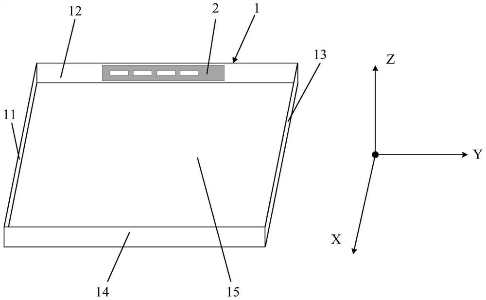
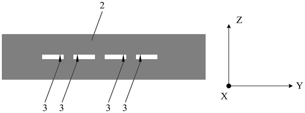
[0019] see figure 1 , figure 1 is a schematic structural diagram of a millimeter wave wireless terminal device provided by an embodiment of the present invention, as shown in figure 1 As shown, it includes a non-conductive housing 1, and a conductive sheet 2 attached to the non-conductive housing 1; the conductive sheet 2 includes a first surface and a second surface, and the first surface is the conductive The side of the sheet 2 attached to the non...


PUM


Abstract

The present invention provides a millimeter-wave wireless terminal device, the millimeter-wave wireless terminal device includes a non-conductive casing, and a conductive sheet attached to the non-conductive casing; the conductive sheet includes a first surface and a second surface , the first surface is the surface where the conductive sheet is attached to the non-conductive housing; the conductive sheet is provided with at least two slits, and the second surface is provided with at least two antenna feeding points, the Different antenna feed points among the at least two antenna feed points are located on sides of different slots. In this way, the conductive sheet provided with the slit is equivalent to the millimeter wave array antenna of the millimeter wave wireless terminal equipment, and the conductive sheet is attached to the non-conductive housing, thereby saving the accommodation space of the millimeter wave antenna and reducing the The size of the wireless terminal equipment has a high degree of conformality between appearance and structure, and it can have a high degree of freedom in the design of the antenna array, so the overall competitiveness of the terminal equipment can be improved.

Description

technical field [0001] The present invention relates to the technical field of communications, in particular to a millimeter-wave wireless terminal device. Background technique [0002] With the rapid development of communication technology, multi-antenna communication has become the mainstream and future development trend of wireless terminal equipment, and with the advent of the 5G (fifth generation mobile communication) era, millimeter wave antennas are gradually being introduced to terminal equipment . In the prior art, the millimeter-wave antenna is generally in the form of a block-shaped independent antenna module, so it is necessary to provide a relatively large accommodation space for the independent antenna module in the terminal device. In this way, the size of the entire terminal equipment tends to be relatively large, and often results in limited product appearance design, or a decline in the performance of related antennas, thus resulting in relatively low over...

Claims


Application Information

Patent Timeline
IPC IPC(8): H01Q21/06H01Q13/10H01Q1/36H01Q1/50H01Q1/24H01Q1/22
CPCH01Q1/22H01Q1/2258H01Q1/242H01Q1/36H01Q1/50H01Q13/10H01Q21/064
Inventor 黄奂衢王义金简宪静
Owner VIVO MOBILE COMM CO LTD
Learn More