Hiccup time control circuit and switching power supply including the same

A time control circuit and control circuit technology, applied in emergency protection circuit devices, electrical components and other directions, can solve problems such as affecting the reliability of switching power supplies, inability to accurately adjust the overcurrent hiccup protection time, damage to power devices, etc. The effect of simple circuit and high control precision

Pending Publication Date: 2018-12-11
MORNSUN GUANGZHOU SCI & TECH
View PDF0 Cites 2 Cited by
  • Summary
  • Abstract
  • Description
  • Claims
  • Application Information

AI Technical Summary

Problems solved by technology

[0004] In order to realize the miniaturization of switching power supply, many switching power supply control ICs integrate over-current hiccup protection function, but the over-current hiccup protection time integrated in many ICs cannot be adjusted accurately, especially for high-power switching power supplies, when over-current or short-circuit hiccup state, its internal power devices are often damaged because they cannot withstand the long working time in the hiccup state, which seriously affects the reliability of the switching power supply

Method used


Image

  • Hiccup time control circuit and switching power supply including the same
  • Hiccup time control circuit and switching power supply including the same
  • Hiccup time control circuit and switching power supply including the same

Examples


no. 1 example

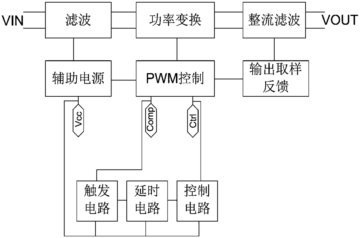
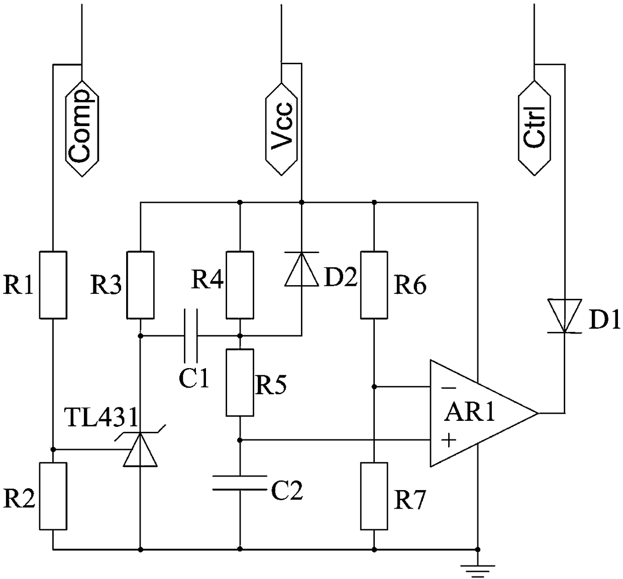
[0034] Such as figure 2 Shown is the schematic diagram of this embodiment, a hiccup time control circuit of a switching power supply, including a trigger circuit, a delay circuit and a control circuit, and also includes a compensation level input terminal Comp, a control terminal, a power supply terminal Vcc and a ground terminal.

[0035] The trigger circuit includes a first resistor R1, a second resistor R2, a third resistor R3, and a first voltage regulator. The first voltage regulator includes a reference terminal, an anode, and a cathode. The connection relationship is: one end of the first resistor R1 is a trigger The input terminal of the circuit, the other end of the first resistor R1 is connected to the reference terminal of the first voltage regulator, and the reference terminal of the first voltage regulator is also connected to the ground terminal through the second resistor R2 (connecting the ground terminal is connected to the ground terminal of the control chip ...

no. 2 example

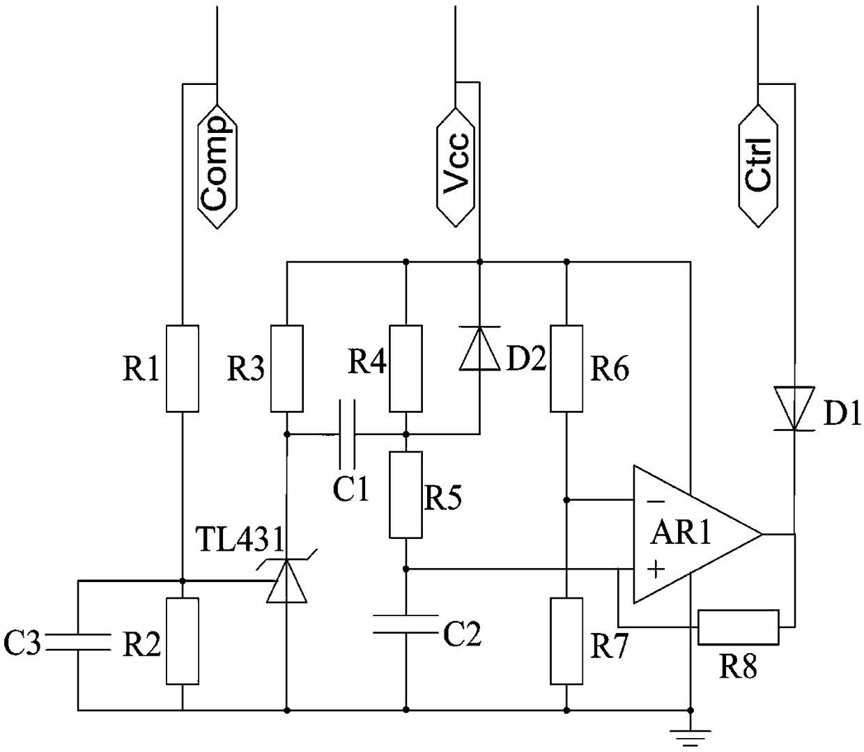
[0048] Such as image 3 Shown is the schematic diagram of the second embodiment, its basic working principle is the same as that of the first embodiment, the main difference is that the trigger circuit adds a third capacitor C3, the third capacitor C3 is connected in parallel with the second resistor R2, and the control circuit adds a third capacitor C3 Eight resistors R8, one end of the eighth resistor R8 is connected to the non-inverting input end of the first operational amplifier AR1, and the other end of the resistor R8 is connected to the output end of the operational amplifier AR1.

[0049] Its working principle differs from that of the first embodiment in that: when the switching power supply does not enter an overcurrent or short-circuit state, the output terminal of the first operational amplifier AR1 is at a high level, and when the switching power supply enters an overcurrent or short-circuit state, the capacitor The voltage across C2 starts to drop slowly from a h...


PUM


Abstract

The invention provides a hiccup time control circuit and a switching power supply comprising the circuit, comprising a trigger circuit, a delay circuit, a control circuit, a compensation level input terminal, a control terminal, a power supply terminal and a ground terminal. When the output of the switching power supply is overcurrent or short circuit, The voltage at the compensation level input rises. As it rise to a first specific value, At that output of the trig circuit, the voltage changes rapidly from a high voltage to a low voltage, As that voltage at the output of the delay circuit decrease slowly from the initial high voltage, When the output voltage of the delay circuit drops to the second specific value, the output of the control circuit turns off the switching power supply through the control terminal, and by adjusting the parameters of the delay circuit, the working time of the switching power supply output over-current or short-circuit hiccup protection can be adjusted. The circuit is simple, the cost is low, and the reliability is high.

Description

Technical field: [0001] The invention relates to the field of power supply circuits, in particular to a hiccup time control circuit and a switching power supply including the circuit. Background technique: [0002] As the core component of modern power conversion technology, switching power supply has been widely used in various power consumption occasions. Whether the switching power supply can operate safely and stably is directly related to circuit safety, equipment safety and even personal safety. Therefore, in the design of switching power supply , Usually a protection circuit is added to ensure the safe and stable operation of the power supply. [0003] During the use of switching power supply, when the output power exceeds its rated power, the reliability of its internal components cannot be guaranteed. Therefore, output overcurrent protection and output short circuit protection circuits are often added to the switching power supply during the design process, hiccup o...

Claims


Application Information

Patent Timeline
IPC IPC(8): H02H7/12
CPCH02H7/1203Y02B70/10
Inventor 张志成王国云冯刚
Owner MORNSUN GUANGZHOU SCI & TECH
Why Eureka
Try Eureka