Spray control method and device, moving device and spray control method of moving device

A technology of spraying control and moving device, which is applied in the direction of program control, watering device, computer control, etc., can solve the problems that the dosage cannot reach the preset target value and the upper limit of the flow rate is low.

Pending Publication Date: 2018-12-14
GUANGZHOU XAIRCRAFT TECH CO LTD
View PDF0 Cites 3 Cited by
  • Summary
  • Abstract
  • Description
  • Claims
  • Application Information

AI Technical Summary

Problems solved by technology

[0004] The purpose of the present invention is to at least solve one of the above-mentioned technical defects, especially the problem that the upper limit of the flow rate of a single spraying structure in the spraying system is low, and the dosage per unit area cannot reach the preset target value during the high-speed movement process.

Method used


Image

  • Spray control method and device, moving device and spray control method of moving device
  • Spray control method and device, moving device and spray control method of moving device
  • Spray control method and device, moving device and spray control method of moving device

Examples


Embodiment 1

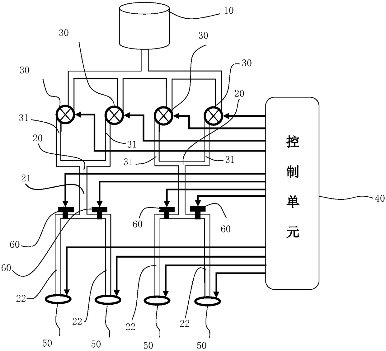
[0103] In the spraying control device provided by the present invention, a spraying structure 50 is provided at the end of the spraying branch 20, and the two or more driving pumps 30 are connected to one spraying structure 50 after being combined. , the opening and stopping of the spraying structure 50 is controlled by the control unit 40. During agricultural use, in order to make objects evenly sprayed on the land (such as particles) or plants (such as liquid), the spraying branch A spraying structure 50 is arranged at the end of the road 20 , and the spraying structure 50 can deliver the driving pump 30 to the spraying structure 50 through the spraying branch 20 . In particular, the spraying structure 50 can be controlled by the control unit 40 so that objects (especially liquids) can be atomized under the action of the spraying structure 50. , when the flow value in the flow information acquired by the control unit 40 is relatively large, and the driven pump 30 cannot reac...

Embodiment 2

[0106] A spray control device provided by the invention, such as figure 1 As shown, the end of the spraying branch 20 is provided with a spraying structure 50, and the two or more than two drive pumps 30 are connected to a plurality of the spraying structures 50 after being combined, and the spraying structures 50 The start and stop are controlled by the control unit 40 .

[0107] Further, as figure 1 As shown, the spray branch 20 is provided with a valve 60 for controlling fluid circulation, and the opening and stopping of the valve 60 is controlled by the control unit 40 .

[0108] Specifically, the storage container 10 is used to store clear water, diluted or undiluted medicinal liquid and other liquids, granular objects, viscous paste and other objects, and the storage container 10 communicates with the driving pump 30 through branch pipelines, wherein each The drive pump 30 is communicated with the storage container 10 through a separate pipeline, or multiple drive pump...


PUM


Abstract

The invention provides a spray control device. The device comprises a storage container, spray branches, drive pumps communicated with the storage container and the spray branch as well as a control unit, wherein after two or more drive pumps are combined, branches are communicated with one or more spray branches; the control unit controls the work state of one or more drive pumps according to flow control information to control the flow of a fluid flowing through the spray branches. The connecting mode of the drive pumps and spray structures is changed on the basis that the number of existingdrive pumps and spray structures is not changed, so that multiple drive pumps can convey liquids to the same spray structure simultaneously, the flow range sprayed by the spray structures is enlarged, the flight speed of an unmanned aerial vehicle is increased, the flow of the spray structures can be increased, the dosage in unit area can reach a target value in the high-speed flight state of theunmanned aerial vehicle, the economic cost is saved, and the operation efficiency of unmanned aerial vehicle plant protection is improved.

Description

technical field [0001] The present invention relates to the field of aviation spraying, plant protection and aircraft, in particular, the present invention relates to a spraying control method and device, a mobile device and a spraying control method thereof. Background technique [0002] With the popularization and use of agricultural drones in my country, the operational effect and efficiency of drones have become the focus of attention of users and R&D personnel. As the core system of the agricultural drone, the spraying system is directly related to the effect of the spraying operation and the efficiency of the operation. A conventional spraying system is mainly composed of a medicine box, a water pump, a nozzle, and pipelines. The water pump is used as the power source for transporting medicine, and its working efficiency directly affects the working efficiency of the entire spraying system. [0003] At present, due to the small size, light weight, easy maintenance, an...

Claims


Application Information

Patent Timeline
IPC IPC(8): A01M7/00A01M9/00A01G25/02G05B19/042
CPCA01G25/02A01M7/0025A01M7/0089A01M9/0053A01M9/0092G05B19/042
Inventor 彭瑾
Owner GUANGZHOU XAIRCRAFT TECH CO LTD
Why Eureka
Try Eureka