Eureka AIR delivers breakthrough ideas for toughest innovation challenges, trusted by R&D personnel around the world.

Quick roll changing device for working roll or supporting roll of hot rolling production line, and changing method

A roll changing device and work roll technology, applied in metal rolling, manufacturing tools, metal rolling, etc., can solve the problems of complex structure design of the transmission device, immature roll changing process, complicated roll changing steps, etc., and improve the equipment Efficiency of use, shortening of working time, and low cost

Inactive Publication Date: 2018-12-14
武汉钢铁有限公司
View PDF8 Cites 6 Cited by
  • Summary
  • Abstract
  • Description
  • Claims
  • Application Information

AI Technical Summary

Problems solved by technology

[0003] The existing four-high rolling mill work roll replacement usually adopts the method of roll changing trolley and online manual hoisting, but this method has the following problems: First, the transmission device structure design of the roll changing trolley is complicated, including direct-connected motor, reducer , chains, sprockets, clutches, drag chains and other equipment, the cost is high; the second is that the traversing mechanism of the roller changing trolley adopts a guide rail roller structure, which has low traversing accuracy and inaccurate positioning, which affects the time of changing rollers; the third is changing rollers The steps are complicated, and the roll changing process is immature. It often happens that the automatic roll changing cannot be completed and the roll changing is changed manually, which increases the time for roll changing

Method used


Image

  • Quick roll changing device for working roll or supporting roll of hot rolling production line, and changing method
  • Quick roll changing device for working roll or supporting roll of hot rolling production line, and changing method
  • Quick roll changing device for working roll or supporting roll of hot rolling production line, and changing method

Examples


Embodiment Construction

[0033] The present invention will be further described in detail below in conjunction with the accompanying drawings and specific embodiments.

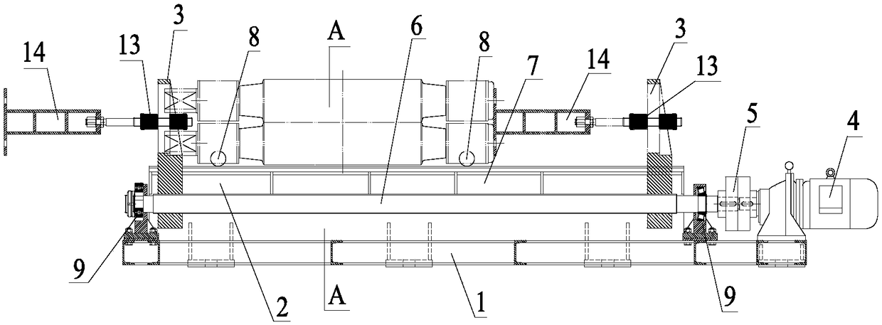
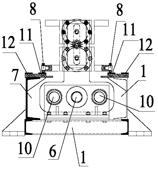
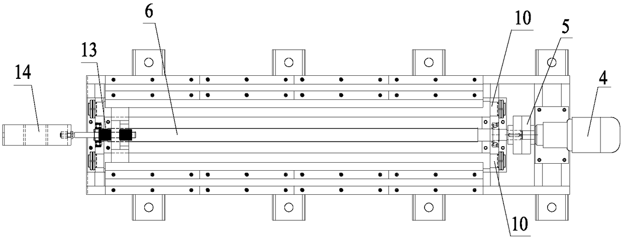
[0034] Such as figure 1 As shown, a quick roll changing device for work rolls or back-up rolls in a hot rolling production line includes a frame 1 on which a sliding frame 2 for placing the working rolls or backup rolls is arranged. The sliding frame 2 includes two symmetrical sliding frames The baffle 3 and the frame 1 are fixed with a cycloidal pinwheel reducer 4, and the cycloidal pinwheel reducer 4 is connected with a screw rod 6 through a column pin coupling 5, and the screw rod 6 passes through two screw rods in sequence. The lower part of the sliding baffle 3, such as figure 2 As shown, the carriage 2 also includes two roll changing platforms 7 parallel to the screw mandrel 6, the two roll changing platforms 7 are respectively located on both sides of the screw mandrel 6, and the upper surfaces of the two roll changing platfo...


PUM


Abstract

The invention relates to the field of hot rolling, and discloses a quick roll changing device for a working roll or a supporting roll of a hot rolling production line. The quick roll changing device for the working roll or the supporting roll of the hot rolling production line comprises a rack, wherein a sliding frame is arranged on the rack and comprises two sliding baffle plates symmetrical leftand right; a cycloidal pin wheel speed reducer is fixedly arranged on the rack and is connected with a screw rod through a pin coupler; the screw rod sequentially penetrates through the lower parts of the two sliding baffle plates through threaded connection; the sliding frame further comprises two roll changing platforms parallel to the screw rod; the two roll changing platforms are located on two sides of the screw rod; and two rows of rollers of the working roller or the support roller are located on the two roll changing platforms. The invention further discloses a changing method of thequick roll changing device for the working roll or the supporting roll of the hot rolling production line. The quick roll changing device for the working roll or the supporting roll of the hot rollingproduction line, and the changing method provided by the invention support the changing of the working roll or the supporting roll, and is accurate in control, fast in roll changing speed and low inworking intensity; and the device is simple in design and low in cost.

Description

technical field [0001] The invention relates to the field of hot rolling, in particular to a quick roll changing device and method for working rolls or backup rolls in a hot rolling production line. Background technique [0002] The four-high rolling mill is the core equipment of the hot rolling production line in the iron and steel industry. After working for a long time, the working rolls (or back-up rolls) will need to be replaced quickly due to wear and tear. In an ordinary hot rolling production line, the work rolls need to be replaced once every 90 strips are rolled, and about 3 times a day. The replacement efficiency of the work rolls directly affects the production capacity of the entire production line. [0003] The existing four-high rolling mill work roll replacement usually adopts the method of roll changing trolley and online manual hoisting, but this method has the following problems: First, the transmission device structure design of the roll changing trolley ...

Claims


Application Information

Patent Timeline
Patent Type & Authority Applications(China)
IPC IPC(8): B21B31/10
Inventor 张雪荣
Owner 武汉钢铁有限公司
Why Eureka
Eureka Blog
Learn More