

Feeding device for metal tube cutting
A feeding device and metal pipe technology, applied in the field of metal pipe processing, can solve the problems of low cutting efficiency, single function, high labor intensity of workers, etc., and achieve the effect of preventing dislocation
- Summary
- Abstract
- Description
- Claims
- Application Information
AI Technical Summary
Problems solved by technology
Method used
Image

Examples
Embodiment 2
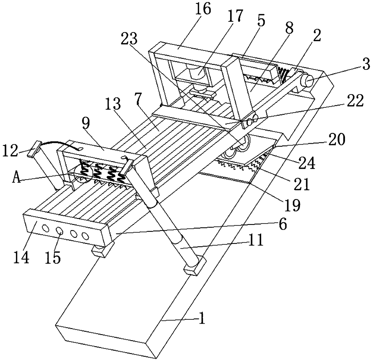
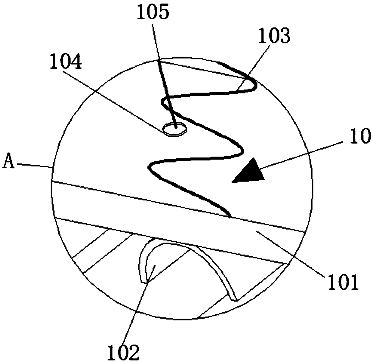
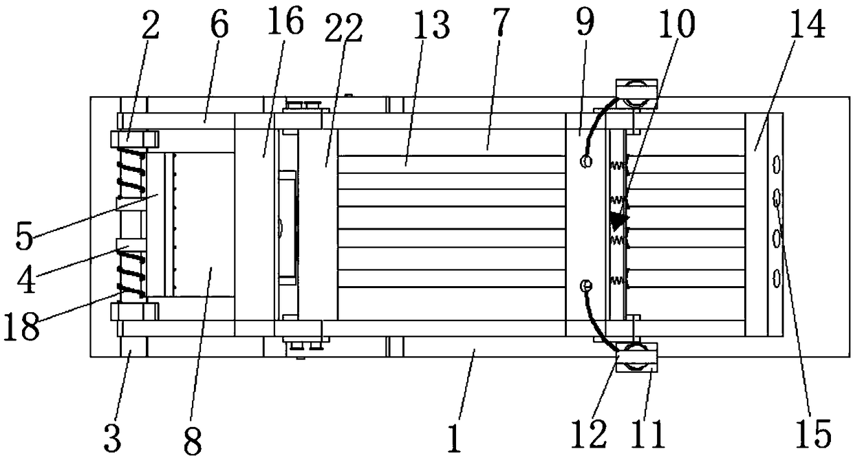
[0032] refer to Figure 1-2 , a feeding device for metal pipe cutting, which is basically the same as that of Embodiment 1, the difference is that two symmetrically distributed electric telescopic rods 11 are connected to the base 1, and the telescopic ends of the electric telescopic rods 11 are connected with connectors 12. A tie ring 104 is also connected to the connecting plate 101, and a stay rope 105 is connected between the tie ring 104 and the connector 12, and the stay rope 105 passes through the first support frame 9, and the feeding plate 7 is provided with evenly distributed The arc-shaped limiting groove 13, the side of the feeding plate 7 away from the workbench 8 is connected with the limiting block 14, the limiting block 14 is provided with evenly distributed limiting holes 15, and the limiting holes 15 and the arc-shaped limiting groove 13 one-to-one correspondence, the metal pipe passes through the limiting hole 15 and enters the arc-shaped limiting groove 13,...
Embodiment 3
[0034] refer to Figure 1-4 , a feeding device for metal pipe cutting, which is basically the same as Embodiment 2, the difference is that the bottom of the feeding plate 7 is slidably connected with a vibration exciter 23, and the bottom of the vibration exciter 23 is connected with an adjustment plate 24, and the base The top of 1 is slidingly connected with a bottom plate 19, the bottom plate 19 is hinged with the adjustment plate 24 through the hinge 20, and the main vibration spring 21 is connected between the bottom plate 19 and the adjustment plate 24, and the vibration exciter 23 is controlled to work, and the vibration exciter 23 drives The main vibration spring 21 vibrates, and then realizes the vibration feeding function of the cutting table 6, and realizes the stable feeding.
Embodiment 4
[0036] refer to Figure 1-4 , a feeding device for metal pipe cutting, which is basically the same as that of Embodiment 3, the difference is that the side of the second support frame 16 close to the first support frame 9 is connected with a limiting plate 22, and the limiting plate 22 is located at the given position. On the top of the material plate 7, it is the limit function to realize the gradual cutting and shortening of the long metal pipe, so as to prevent dislocation and improve the stability of material delivery.
PUM
 Abstract
Description
Claims
Application Information