RTM (resin transfer molding) mold for partition type rotating structure composite parts

A composite material and rotary structure technology, which is applied to household components, household appliances, and other household appliances, can solve the problems of poor rigidity of the inner mandrel, unsuitable RTM molding process, and easy deformation, so as to reduce manufacturing costs and improve internal and external surfaces. The effect of excellent quality and high dimensional accuracy

Active Publication Date: 2018-12-14
AVIC BASIC TECH RES INST +1
View PDF5 Cites 7 Cited by
  • Summary
  • Abstract
  • Description
  • Claims
  • Application Information

AI Technical Summary

Problems solved by technology

The above solutions are all based on the integrated inner core mold forming scheme, but the inner core mold has poor rigidity and is easy to deform under high temperature and high pressure, and the profile of composite parts cannot be effectively guaranteed, so it is not suitable for RTM molding process

Method used


Image

  • RTM (resin transfer molding) mold for partition type rotating structure composite parts
  • RTM (resin transfer molding) mold for partition type rotating structure composite parts
  • RTM (resin transfer molding) mold for partition type rotating structure composite parts

Examples


preparation example Construction

[0037] The preparation process of the composite parts with segmental plus rotation structure is as follows:

[0038] (1) Lay the dry pre-shaped fabric on the boss 2-1 of the lower mold 2 according to the design, and perform vacuum pre-setting on the flange prefabricated body after the paving is completed;

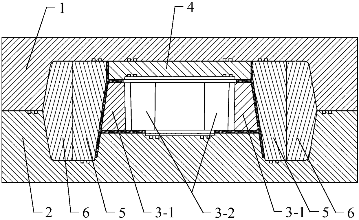
[0039] (2) Connect the U-shaped core mold 3-1 and the C-shaped forming mold 3-2 through bolts to form a combined inner core mold 3 in the middle section, and lay the outer layer of the C-shaped forming mold 3-2 according to the design. C-type prefabricated body, and preform the prefabricated body in vacuum;

[0040] (3) Place the combined inner core mold 3 of the middle partition section in the positioning groove 2-2 of the lower mold 2, and carry out vacuum pre-setting on the lower mold 2 and the combined inner core mold 3 of the middle partition section, so that the middle partition section is combined The type inner mandrel 3 completes precise positioning in the positio...

specific Embodiment 1

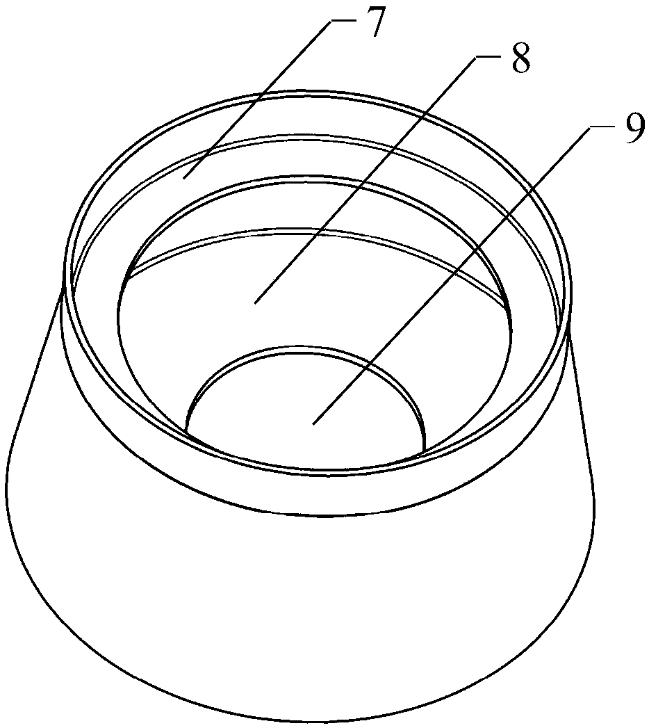
[0047] Typical structure such as figure 1 As shown, the three-section rotary structure composed of upper and lower flanges has dimensions: height 200mm, diameter of the large end 400mm, and diameter of the small end 300mm. It is prepared by dry pre-shaped fabric, and then injected with low-viscosity resin through the RTM process. , and finally solidify into shape. We have adopted the solution of the present invention, and all components of the mold are made of P20 steel.

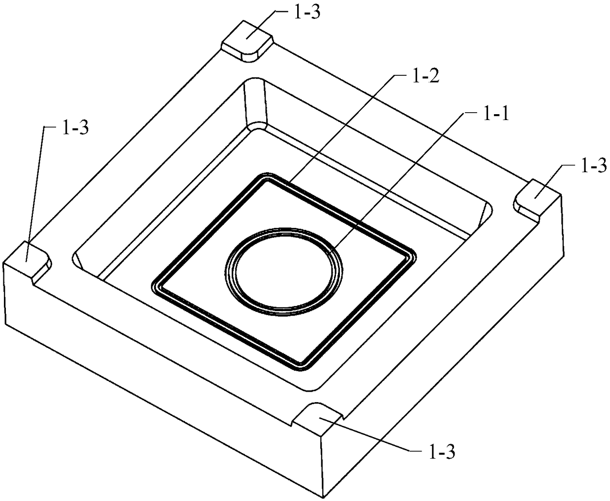
[0048] The upper mold 1 is designed as a female mold, and the slope of the upper mold 1 side to the inner surface is 15°; the bottom surface is a plane, and the sealing grooves 1-1 and 1-2 designed on the bottom plane have a width of 4.5mm and a depth of 5.5mm; the length of the mouth positioning table 1-3 is 40mm, the width is 50mm, the height is 10mm, and the slope is 10°;

[0049] The lower mold 2 is designed as a female mold, and the slope of the inner surface of the lower mold 2 is 15°; the bottom sur...


PUM

PropertyMeasurementUnit
Lengthaaaaaaaaaa
Widthaaaaaaaaaa
Depthaaaaaaaaaa

Abstract

The invention belongs to the technical field of molding of resin-based composites and relates to an RTM (resin transfer molding) mold for partition type rotating structure composite parts. The mold comprises an upper mold, a lower mold, a middle partition combined type inner mandrel, an upper partition inner mandrel, an outer mold and moving sliders. During mold assembly, the middle partition combined type inner mandrel is placed into a positioning groove of the lower mold firstly, then the upper partition inner mandrel is placed on the middle partition combined type inner mandrel, the outer mold is placed on the bottom surface of the lower mold, the moving sliders are placed on the periphery of the outer mold, the upper and the lower mold are assembled oppositely, the gap between the upper mold and the lower mold is reduced gradually under the fastening effect of bolts, and the moving sliders move in plane to enable the outer mold to be placed in a theoretical position under the action of lateral inner mold surfaces of the upper mold and the lower mold. By design of the combined steel inner mandrels, the mandrels can be prevented from falling out of the inner cavities of the semi-closed partitions, and dimensional accuracy of the inner mold surfaces and flanges of the rotating structure is guaranteed.

Description

technical field [0001] The invention belongs to the technical field of resin-based composite material molding, and relates to an RTM molding die for segmental rotary structure composite material parts. Background technique [0002] Advanced resin matrix composites have the unique advantages of high specific strength and specific stiffness, strong designability, excellent corrosion resistance, and easy large-area integral molding, making them an indispensable strategic material in the structure of aerospace vehicles. The extensive application of composite materials in aviation weaponry can effectively improve performance, reduce structural weight, reduce operating costs, and enhance market competitiveness. Advanced composite materials are increasingly used in aircraft structures. On the one hand, the proportion of composite materials used in military and civilian aircraft continues to increase; on the other hand, the application of advanced composite materials has developed ...

Claims


Application Information

Patent Timeline
IPC IPC(8): B29C70/48B29C70/54B29C33/38B29L31/30
CPCB29C33/3842B29C70/48B29C70/54B29L2031/3076
Inventor 李伟东包建文罗楚养钟翔屿李晔张朋秦永乐邹豪
Owner AVIC BASIC TECH RES INST
Why Eureka
Try Eureka