Non-contact air flotation claw device

A non-contact, air flotation technology, applied in the direction of transportation and packaging, conveyor objects, furnaces, etc., can solve the problems of cross-contamination and scratches on glass substrates, achieve simple structure, solve cross-contamination, and stable and reliable transportation process Effect

Active Publication Date: 2018-12-14
通彩智能科技集团有限公司
View PDF7 Cites 2 Cited by
  • Summary
  • Abstract
  • Description
  • Claims
  • Application Information

AI Technical Summary

Problems solved by technology

[0004] In view of the above problems in the prior art, it aims to provide a non-contact air flotation claw device, which can transport the glass substrate by means of gas suspension, which solves the cross-contamination and scratches caused by the previous glass substrate handling process. And other issues

Method used


Image

  • Non-contact air flotation claw device
  • Non-contact air flotation claw device
  • Non-contact air flotation claw device

Examples


Embodiment 1

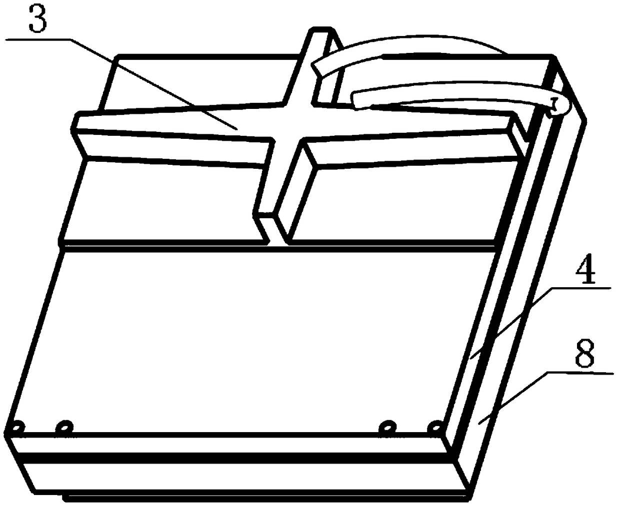
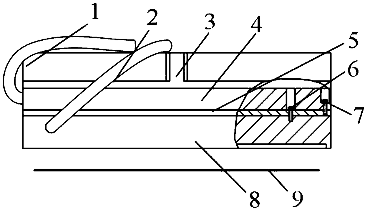
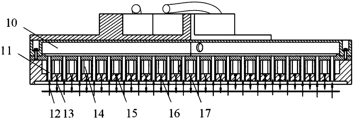
[0030] figure 1 It is a perspective view of an embodiment of a non-contact air bearing claw device of the present invention; figure 2 It is a front view of an embodiment of a non-contact air bearing claw device of the present invention; image 3 It is a cross-sectional view of Embodiment 1 of a non-contact air bearing claw device of the present invention; Figure 4 It is a bottom view of Embodiment 1 of a non-contact air bearing claw device of the present invention. In this embodiment, the non-contact air flotation claw device mainly includes negative pressure air pipe 1, positive pressure air pipe 2, air flotation suction cup adapter 3, negative pressure housing 4, negative pressure adapter plate 5, thread tight Firmware 6, threaded fasteners 7, positive pressure housing 8, glass substrate 9, negative pressure air cavity 10, negative pressure orifice 11, negative pressure air flow 12, positive pressure air flow 13, positive pressure air cavity 14, positive pressure Buffer...

Embodiment 2

[0041] figure 1 It is a perspective view of an embodiment of a non-contact air bearing claw device of the present invention; figure 2 It is a front view of an embodiment of a non-contact air bearing claw device of the present invention; Figure 5 It is a cross-sectional view of Embodiment 2 of a non-contact air bearing claw device of the present invention; Figure 6 It is a bottom view of Embodiment 2 of a non-contact air bearing claw device of the present invention. In this embodiment, the non-contact air flotation claw device mainly includes negative pressure air pipe 1, positive pressure air pipe 2, air flotation suction cup adapter 3, negative pressure housing 4, negative pressure adapter plate 5, thread tight Firmware 6, threaded fastener 7, positive pressure housing 8, glass substrate 9, negative pressure air cavity 20, negative pressure microhole 21, negative pressure airflow 22, positive pressure airflow 23, positive pressure microhole 24, positive pressure Micropo...


PUM


Abstract

The invention discloses a non-contact air flotation claw device, and belongs to the technical field of air flotation transportation. The non-contact air flotation claw device comprises a negative pressure shell, a positive pressure shell and an air flotation suction disc adapter, wherein the negative pressure shell is connected with a negative pressure air pipe, a negative pressure air cavity is formed in the negative pressure shell, and the negative pressure air cavity communicates with the negative pressure air pipe; the positive pressure shell is connected with a positive pressure air pipe,a positive pressure air cavity is formed in the positive pressure shell, the positive pressure air cavity communicates with the positive pressure air pipe, a plurality of negative pressure air holesand a plurality of positive pressure air holes are formed in the lower end surface of the positive pressure shell, the positive pressure air holes communicate with the positive pressure air cavity, and the negative pressure air holes communicate with the negative pressure air cavity; or a plurality of negative pressure air holes and positive pressure micropore breathable composite materials are arranged at the lower end surface of the positive pressure shell; and the air flotation suction disc adapter is arranged on the upper end surface of the negative pressure shell. The non-contact air flotation claw device is simple in structure, environment-friendly and clean, and solves the problems of pollution and scratch caused by a glass substrate in the conveying process.

Description

technical field [0001] The invention relates to the technical field of air flotation transportation, in particular to a non-contact air flotation claw device. Background technique [0002] At present, with the rapid development of flat panel display technology, the requirements for automatic equipment for transporting glass substrates are getting higher and higher. The size of the glass substrate is gradually increasing and the thickness is decreasing. The high stability, high speed, and high cleanliness of glass substrate handling can improve production efficiency, which is of great significance to the mass production of the FPD industry. [0003] The glass handling robot is an automatic equipment for handling glass substrates in the PFD industry. However, the end effectors of most glass robots are grasped in a contact manner. This method can meet the high stability and high-speed requirements of glass substrate handling, but the contact grabbing method in the front and ...

Claims


Application Information

Patent Timeline
IPC IPC(8): B65G49/06
CPCB65G49/065
Inventor 贺小平张佳许鹤华徐志法
Owner 通彩智能科技集团有限公司
Why Eureka
Try Eureka