Oil pressure buffer

A technology of oil pressure buffer and cylinder block, which is applied in the field of oil pressure buffer, can solve the problems of increasing the gap between the throttle ring and the throttle cone rod, long oil pressure time, etc., to increase the oil inlet rate and oil refueling speed Improve and increase the effect of oil intake

Inactive Publication Date: 2018-12-14
镇江朝阳机电科技有限公司
View PDF7 Cites 2 Cited by
  • Summary
  • Abstract
  • Description
  • Claims
  • Application Information

AI Technical Summary

Problems solved by technology

[0005] Technical effect: the invention increases the gap between the throttle ring and the throttle cone rod, and sets communication holes with different apertures above and below the throttle ring to increase the oil inlet rate and oil inlet volume, thereby significantly increasing the fueling speed , Solve the problem that the oil pressure buffer takes too long to fill the hydraulic oil

Method used


Image

  • Oil pressure buffer
  • Oil pressure buffer
  • Oil pressure buffer

Examples


Embodiment Construction

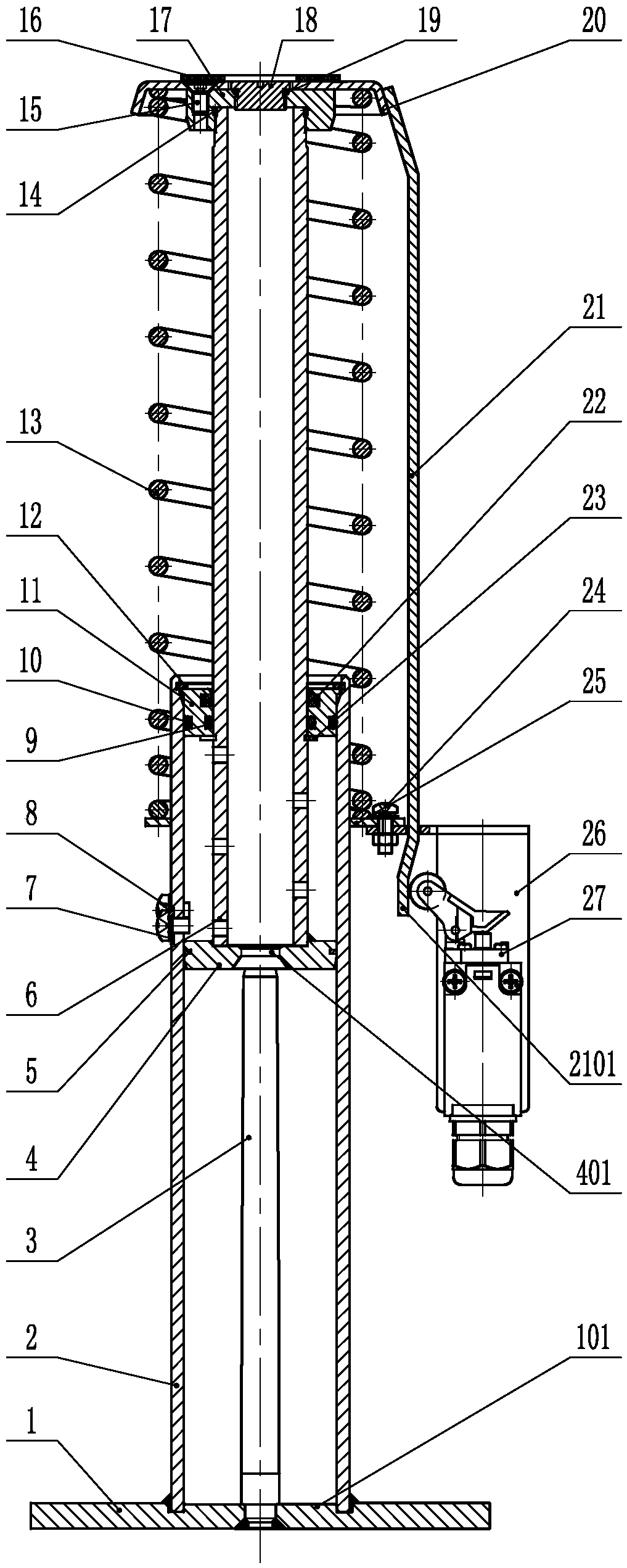
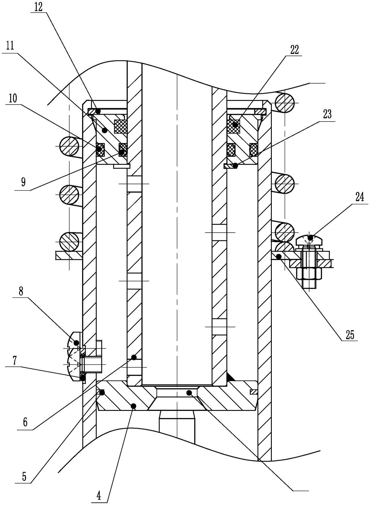
[0032] A high-tightness oil pressure buffer provided in this embodiment has a structure such as Figure 1-3 As shown, including cylinder 2, piston 4, and piston rod 6, the side of piston 4 in contact with cylinder 2 is provided with an annular groove, and a piston ring 5 is embedded in the annular groove. It is tightly attached to the inner wall of the cylinder body 2 and is in a sealed state, and the piston 4 and the piston rod 6 are fixedly connected by spot welding.

[0033] The piston 4 is provided with an inclined surface near the bottom edge, and the inclined surface and the inner wall of the cylinder body 2 form a pre-lubrication space, and the piston ring 5 is located in the center between the highest point of the inclined surface and the highest point of the piston 4 .

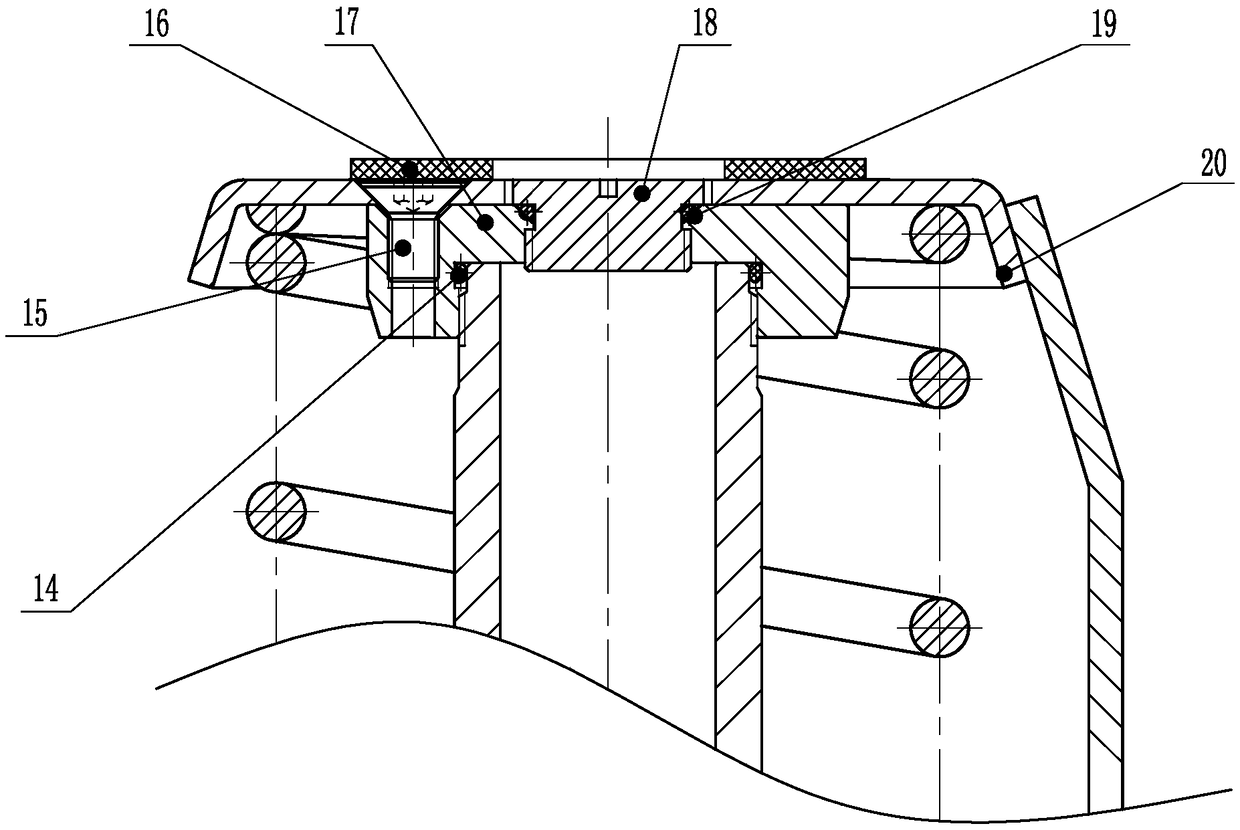
[0034] It also includes a buffer plate 16, an end cover 17, a sealing screw plug 18, an upper spring seat 20, a lower spring seat 25 and a compression spring 13. The end cover 17 is wrapped on the to...


PUM


Abstract

The invention discloses an oil pressure buffer, and relates to the technical field of elevator safety components. The oil pressure buffer comprises a cylinder body, a piston, a piston rod, a throttlering and a throttle cone rod, wherein the throttle ring is positioned in the center of the piston; the throttle cone rod is installed in the cylinder body below the piston; the inner diameter of the throttle ring is larger than the outer diameter of the throttle cone rod and the throttle ring and the throttle cone rod are coaxially arranged; a first communication hole is formed in the bottom of the piston rod; a second communication hole positioned above the throttle ring is formed in the center of the top of the piston; a third communication hole positioned below the throttle ring is formed in the center of the bottom of the piston; and the first communication hole, the second communication hole and the throttle ring communicate with the third communication hole in sequence. According tothe oil pressure buffer, a gap between the throttle ring and the throttle cone rod is increased, and communication holes with different pore diameters are formed in the upper portion and the lower portion of the throttle ring, so that the oil feeding rate and the oil feeding amount are increased, the oil feeding speed is obviously improved, and the problem that the oil pressure buffer takes too long to fill hydraulic oil is solved.

Description

technical field [0001] The invention relates to the technical field of elevator safety components, in particular to an oil pressure buffer. Background technique [0002] Elevator is a kind of vertical elevator powered by electric motor, equipped with box-shaped gondola, which is used for multi-storey buildings to take people or carry goods. There is also a step type, the tread plate is installed on the crawler belt and runs continuously, commonly known as an escalator or moving sidewalk, and serves as a fixed lifting device for a specified floor. The vertical elevator has a car that runs between at least two vertical or rigid guide rails with an inclination angle of less than 15°. The size and structure of the car are convenient for passengers to enter and exit or to load and unload goods. It is customary to use elevator as a general term for vertical transportation in buildings regardless of its driving mode. According to the speed, it can be divided into low-speed elevat...

Claims


Application Information

Patent Timeline
Patent Type & Authority Applications(China)
IPC IPC(8): B66B5/28
Inventor 刘全和
Owner 镇江朝阳机电科技有限公司
Why Eureka
Try Eureka