Mechanized earth-removing machine and soil-removing method for rice seedling raising soil
A technology for raising soil for rice seedlings and borrowers, which is applied in the directions of earth movers/shovels, construction, etc., can solve the problems of poor operation quality, high production cost, low operation efficiency, etc., and achieves high operation efficiency and low operation cost. , the effect of low labor intensity
- Summary
- Abstract
- Description
- Claims
- Application Information
AI Technical Summary
Problems solved by technology
Method used
Image
Examples
Embodiment 1
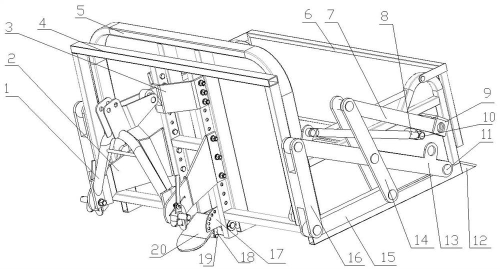
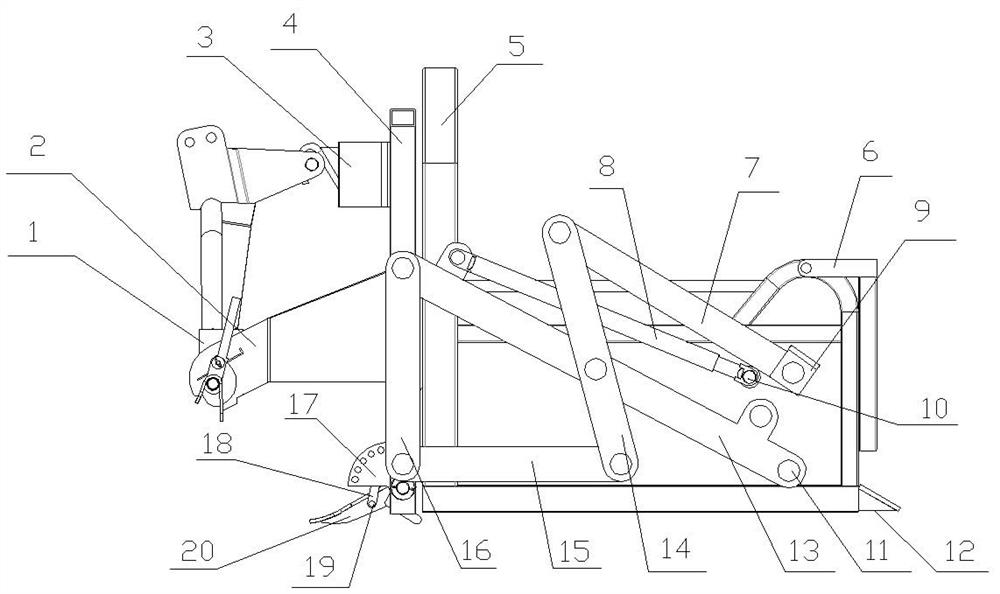
[0027] The upper suspension welding 3 and the lower suspension assembly 2 are installed on the front sub-beam welding 4, the two sides of the lower end of the quick-connect suspension frame 1 are assembled with the lower suspension assembly 2, the upper end is assembled with the upper suspension welding 3, and the front auxiliary The lower part of the beam welding 4 is hinged with the soil-taking shovel welding 20, and the two vertical beams of the front sub-beam welding 4 on both sides of the soil-taking shovel are welded with a soil-taking shovel angle adjustment plate 17, and the soil-taking shovel is welded The middle section is hinged with soil-borrowing shovel positioning pin 19, and soil-borrowing shovel locating pin 19 is hinged at one end of soil-borrowing shovel angle adjustment lever 18, and one end is hinged with soil-borrowing shovel positioning pin 19. The angle of entry into the soil can be adjusted.
Embodiment 2
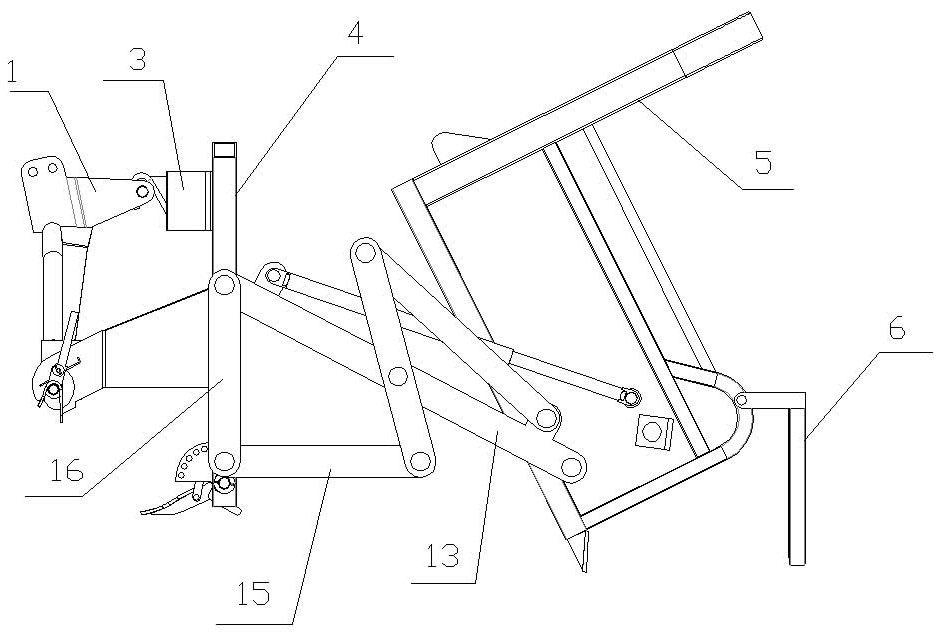
[0029] On the main frame welding 5, for assembling, there are shift rod fixing seats 9, hydraulic cylinder push rod fixing seats 10 and oblique beam hinged shaft seats 11 welded sequentially from top to bottom. The rear end of the main frame is welded 5 and the horizontal frame body of the seal plate welded 6 at the elbow position at the rear is hinged.
Embodiment 3
[0031] Welding 4 both sides of the front sub-beam are welded with link mechanism fixed beam 16, and the upper end of link mechanism fixed beam 16 is hinged with link mechanism oblique beam 13, and the lower end is hinged with link mechanism longitudinal beam 15 front ends; The lower end of the beam 14 is hinged with the rear end of the longitudinal beam 15 of the linkage mechanism, the middle section of the vertical beam 14 in the linkage mechanism is hinged with the middle section of the inclined beam 13 of the linkage mechanism, and the upper end is hinged with one end of the displacement rod 7, and the inclined beam of the linkage mechanism 13 The middle section is hinged with the vertical beam 14 in the linkage mechanism, the rear end is hinged with the inclined beam hinged shaft seat 11, the push rod of the hydraulic cylinder 8 is hinged with the hydraulic cylinder push rod fixing seat 10, and the cylinder barrel of the hydraulic cylinder 8 is hinged on the connecting rod ...
PUM
 Abstract
Description
Claims
Application Information
 - R&D
- Intellectual Property
- Life Sciences
- Materials
- Tech Scout
- Unparalleled Data Quality
- Higher Quality Content
- 60% Fewer Hallucinations
Browse by: Latest US Patents, China's latest patents, Technical Efficacy Thesaurus, Application Domain, Technology Topic, Popular Technical Reports.
© 2025 PatSnap. All rights reserved.Legal|Privacy policy|Modern Slavery Act Transparency Statement|Sitemap|About US| Contact US: help@patsnap.com


