floor drain for bathroom

A floor drain and bathroom technology, applied in the field of kitchen and toilet products, can solve the problems of unfavorable use, easy accumulation, and difficult cleaning of floor drain hair, etc., and achieve the effects of being convenient for long-term use, less peculiar smell, and simple in structure

Inactive Publication Date: 2020-06-12
NANJING LISHUI HIGH-TECH VENTURE CAPITAL MANAGEMENT CO LTD
View PDF1 Cites 2 Cited by
  • Summary
  • Abstract
  • Description
  • Claims
  • Application Information

AI Technical Summary

Problems solved by technology

[0006] Aiming at the deficiencies of the prior art, the present invention provides a special floor drain for the bathroom, which solves the problems that the hair in the floor drain in the bathroom is difficult to clean, easy to accumulate and unfavorable to use

Method used


Image

  • floor drain for bathroom
  • floor drain for bathroom
  • floor drain for bathroom

Examples


Embodiment 1

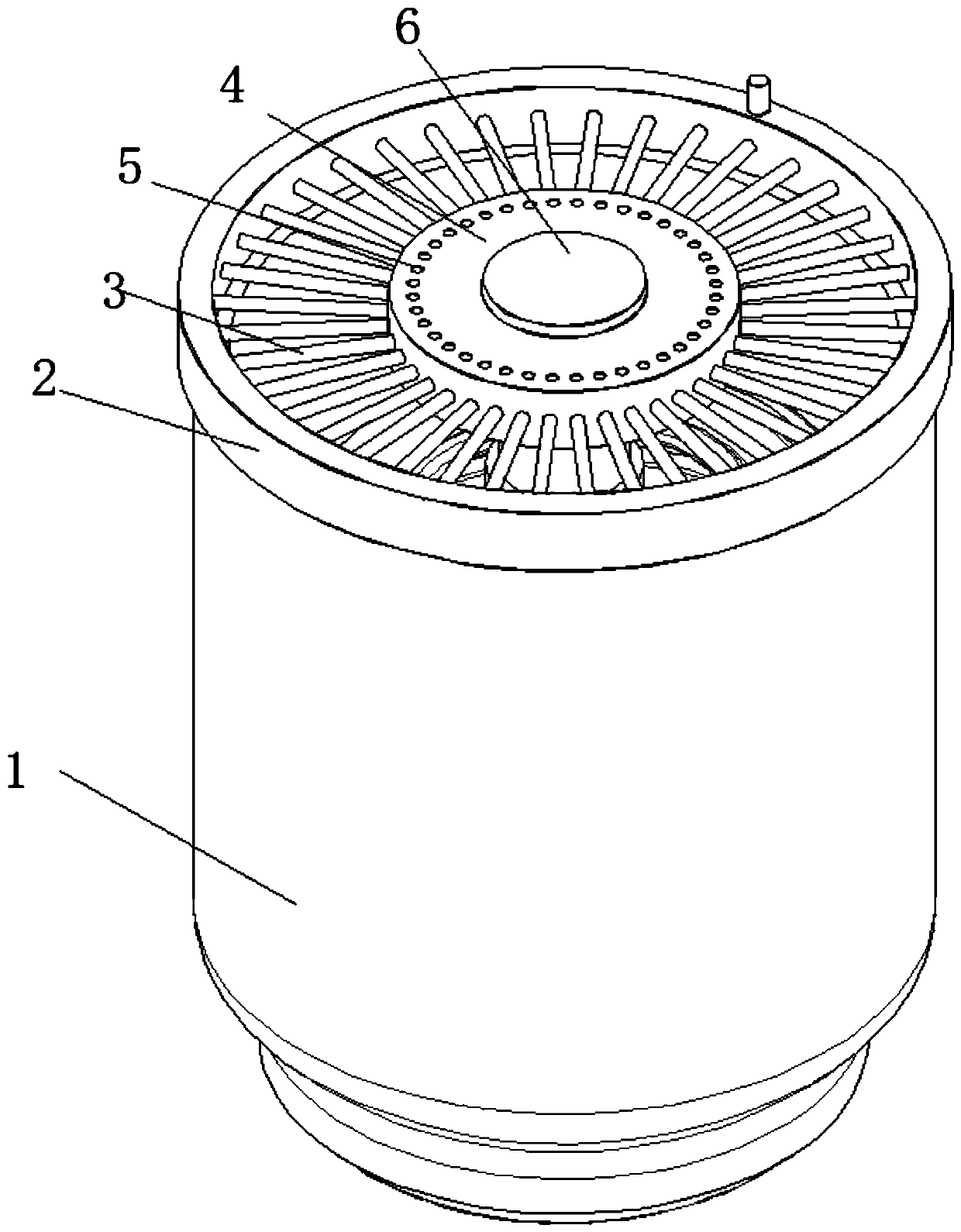
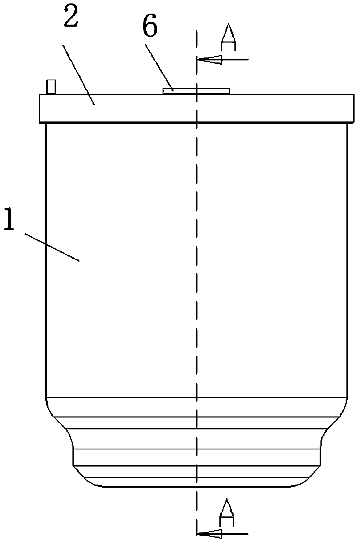
[0042] Such as Figure 1-7 As shown, the present invention provides a technical solution: a special floor drain for bathrooms, including a floor drain body 1, the top and bottom of the floor drain body 1 are open, and the inside of the floor drain body 1 is hollow, and the top of the floor drain body 1 is fixed. Connected with an annular clamping plate 2, a number of connecting rods 3 are fixedly connected between the inner sides of the annular clamping plate 2, setting the connecting rods 3 can preliminarily prevent some large-scale garbage from entering the sewer pipe inside the floor drain, and the number of connecting rods 3 is 20 and two adjacent connecting rods 3 are equidistantly arranged, and the spacing is small, so that it is not easy for large objects to enter the interior to form a blockage. An annular plate 4 is arranged between a plurality of connecting rods 3, and the annular plate 4 The top of the top is provided with a leak hole 5, and water flow can also flow...

Embodiment 2

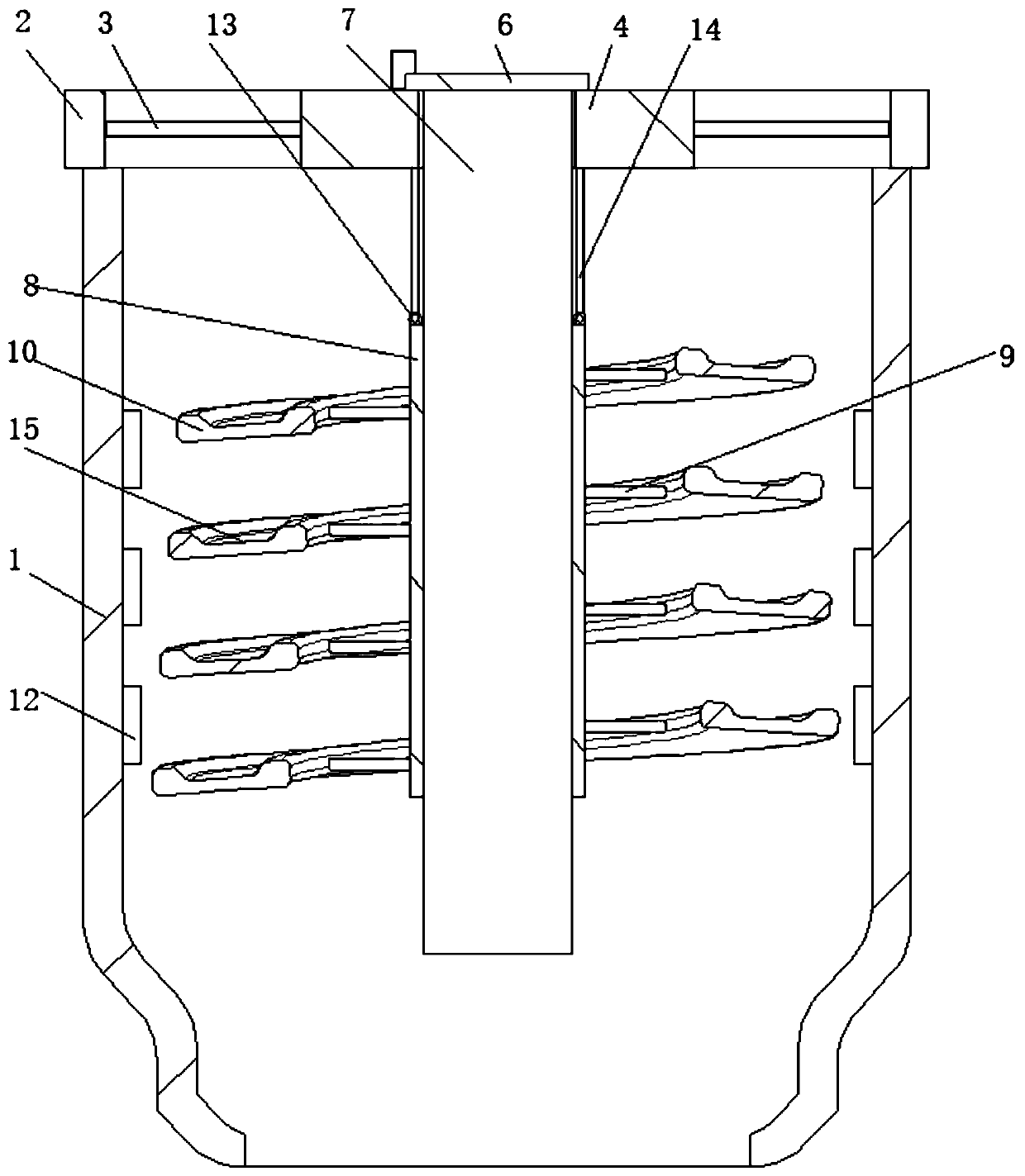
[0045] Such as Figure 1-7 As shown, on the basis of Embodiment 1, the present invention provides a kind of technical scheme: the pitch of the slide plate 10 of spiral setting is 2-3 centimeters, and the spiral outer diameter of slide plate 10 of spiral setting increases successively from top to bottom, so that in During the diversion process, the pressure of the upper water flow is greater than the pressure of the lower water flow, which is convenient for the concentrated water flow to clean up the accumulated hair. The number of spiral turns of the spirally arranged slide plate 10 is 8-10, and the vertical The height is 8-10 cm.

Embodiment 3

[0047] Such as Figure 1-7 As shown, on the basis of Embodiment 1 and Embodiment 2, the present invention provides a technical solution: the upper surface of the spirally arranged slide plate 10 is provided with a diversion groove 15, and the cross section of the diversion groove 15 is semicircular. The hair can be cleaned up intensively, and the diversion operation is carried out from the diversion groove 15 to facilitate the cleaning of the hair inside the floor drain.


PUM


Abstract

The invention relates to the technical field of sanitary ware accessories, in particular to a floor drain special for a shower room and a use method. The floor drain comprises a floor drain body, theupper portion and the lower portion of the floor drain body are in opening shapes, the interior of the floor drain body is hollow, the upper portion of the floor drain body is fixedly connected with an annular clamping plate, multiple connecting rods are fixedly connected between the inner sides of the annular clamping plate, the connecting rods can primarily block some large garbage from enteringa sewer line in the floor drain, an annular plate is mounted among the connecting rods, the problems that hair in a floor drain in an existing shower room is hard to clean and easily stacked and useis not facilitated can be solved, the design is ingenious, the structure is simple, gravity and rotating force of water flow falling can be used, the floor drain is superior to the prior art, the flowguide effect is achieved, blockage is not prone to happening, the hair can be cleaned, the floor drain is completely superior to the prior art, the long-time use is facilitated, and peculiar smell isnot generated.

Description

technical field [0001] The invention relates to the technical field of kitchen and sanitary products, in particular to a special floor drain for bathrooms. Background technique [0002] The floor drain is an important interface connecting the drainage system with the indoor ground. Especially in the bathroom, due to people's metabolism in daily life, hair will fall off when washing hair, and these hairs flow into the floor drain with the water flow, and after entering the pipeline, it is easy to cause blockage of the drainage pipeline. However, cleaning the drainage pipeline Internal blockage is very troublesome work. [0003] Chinese patent CN204608960U discloses a floor drain with a hair-collecting function, in which sewage is diverted through a diversion structure so that debris such as hair is accumulated in the hair collection area. But this operation is difficult to collect the hair in the floor drain only by using the diversion structure. If some remain in the floor...

Claims


Application Information

Patent Timeline
Patent Type & Authority Patents(China)
IPC IPC(8): E03F5/04
CPCE03F5/0407E03F5/041
Inventor 张雨龙
Owner NANJING LISHUI HIGH-TECH VENTURE CAPITAL MANAGEMENT CO LTD
Why Eureka
Try Eureka