Multi-line laser radar calibration method

A technology of laser radar and multi-line laser, which is applied to radio wave measurement systems and instruments, can solve the problems of low scalability, low precision, and high precision requirements, and achieve convenient operation, high calibration efficiency, and improved calibration accuracy Effect

Active Publication Date: 2018-12-14
BEIJING ZHIXINGZHE TECH CO LTD
View PDF5 Cites 35 Cited by
  • Summary
  • Abstract
  • Description
  • Claims
  • Application Information

AI Technical Summary

Problems solved by technology

[0007] Although the principle of manual measurement and calibration method is simple, it has high requirements on the fineness of the operator's operation and the accuracy of the measuring instrument, so its generalizability is not high, and the measurement accuracy is unstable, which will vary with the level of the operator
The measureme

Method used


Image

  • Multi-line laser radar calibration method
  • Multi-line laser radar calibration method
  • Multi-line laser radar calibration method

Examples


Embodiment Construction

[0050] In order to make the object, technical solution and advantages of the present invention clearer, the present invention will be further described in detail below in conjunction with the accompanying drawings. Obviously, the described embodiments are only some embodiments of the present invention, rather than all embodiments . Based on the embodiments of the present invention, all other embodiments obtained by persons of ordinary skill in the art without making creative efforts belong to the protection scope of the present invention.

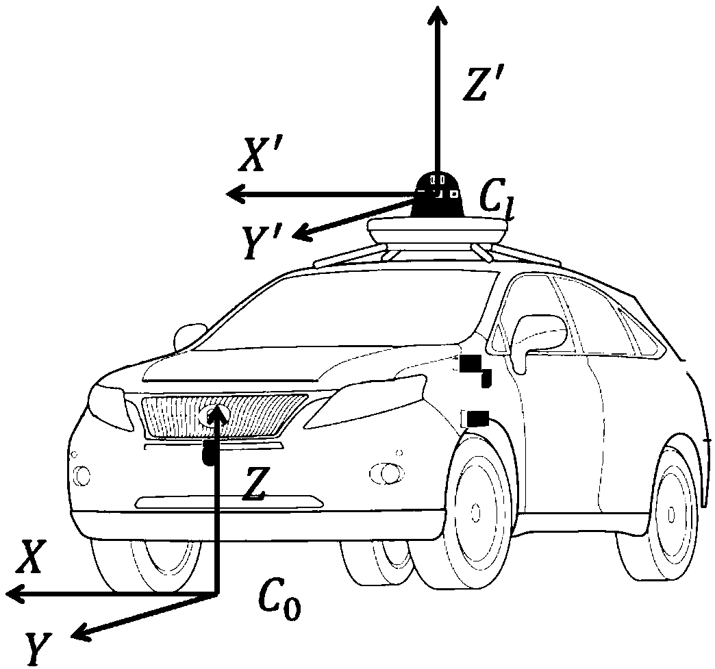
[0051] figure 1 It is a schematic diagram of the relative position relationship of the coordinate system provided by the embodiment of the present invention. Such as figure 1As shown, the lidar coordinate system x′y′z′ is denoted as C l , car body coordinate system xyz denoted as C 0 , the origin of the car body coordinate system is set to the projection point of the center point of the front of the car on the ground, and the xy plane o...


PUM


Abstract

The invention relates to a multi-line laser radar calibration method. The multi-line laser radar calibration method comprises the following steps that two parameters are calibrated by decoupling alpha, beta, delta <z> and gamma, delta <x>, delta <y> respectively; parameters alpha, beta and delta <z> are calibrated by extracting horizontal ground features; and the constraint equations are constructed by rotation matrix v<R> and the translation matrix v<T> provided by GPS, and calibration parameters gamma, delta <x> and delta <y> are solved. According to the multi-line laser radar calibration method, manual measurement of calibration parameters is not required, special calibrated objects are not required, operation is convenient, and calibration efficiency is high. Calibration accuracy can be improved by using flatland features and high precision GPS information.

Description

technical field [0001] The invention relates to the technical field of laser radar, in particular to a multi-line laser radar calibration method. Background technique [0002] In recent years, with the rapid development of intelligent driving technology, lidar has the characteristics of high precision, large ranging range, and not being affected by light, and is widely used in obstacle detection, real-time positioning and map construction of intelligent driving vehicles. perception field. [0003] In the intelligent driving system, the lidar is generally installed on the top of the intelligent driving vehicle, and the position data information obtained by the lidar is based on the local coordinate system of the radar itself. In the actual use of lidar, in order to unify the information of multiple sensors, it is necessary to convert the data in the local coordinate system acquired by the lidar to the car body coordinate system. During the data conversion process, the point...

Claims


Application Information

Patent Timeline
IPC IPC(8): G01S7/497
CPCG01S7/497
Inventor 张德兆王肖李晓飞张放霍舒豪
Owner BEIJING ZHIXINGZHE TECH CO LTD
Why Eureka
Try Eureka