
Overflow control method for city intersection based on wide area radar microwave detector

A microwave detector and intersection technology, applied in the field of intelligent transportation, can solve problems such as high labor costs, undetectable areas or cross-sections, and blocked observation ranges, and achieve real-time and reliability improvements, and simple and efficient control algorithms

Active Publication Date: 2018-12-14
NORTH CHINA UNIVERSITY OF TECHNOLOGY
View PDF25 Cites 27 Cited by
  • Summary
  • Abstract
  • Description
  • Claims
  • Application Information

AI Technical Summary

Problems solved by technology

At the same time, traffic information is not smooth. Travelers still use empirical methods in travel decision-making, relying on past experience, and there is little targeted information that can assist travelers to make the most correct travel choices. The smoothness of information greatly limits urban traffic. Reasonable allocation of resources
[0003] Deficiencies in the prior art: 1. Most of the devices for collecting traffic information rely on the loop coil detectors installed under the road surface. Have equipment and give full play to its advantages and characteristics, and the embedding of coils needs to dig out the road surface to cause damage to the original road surface
The main problem of the geomagnetic detector is that the detection range only exists at points, and it cannot detect areas or sections, and cannot effectively control the operating status in the area
Cross-section microwave technology is used to detect traffic flow data on a certain section of the road. This detection equipment has similar functions to geomagnetic detectors and other equipment, and cannot effectively evaluate the traffic operation status of road sections.
When there is heavy fog, heavy rain or heavy snow, the observation range of the video monitor is blocked, and only relying on the video detection error is large and the labor cost is large

Method used


Image

  • Overflow control method for city intersection based on wide area radar microwave detector
  • Overflow control method for city intersection based on wide area radar microwave detector
  • Overflow control method for city intersection based on wide area radar microwave detector

Examples


Embodiment Construction

[0030] (1) Definition of intersection overflow

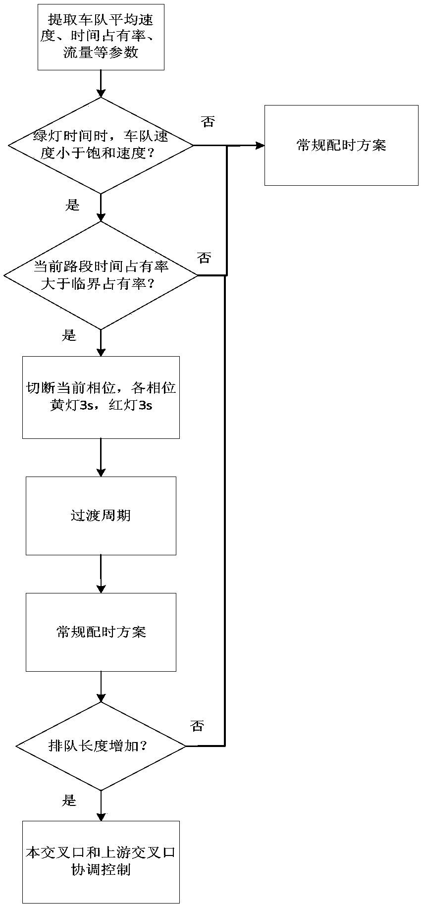
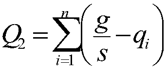
[0031] For a single intersection, the number of queuing vehicles in the through lane of the entrance road is Q 1 , the remaining capacity of the exit channel is Q 2 (That is, the green light phase can accommodate the number of vehicles entering the exit lane in a single cycle). When Q 1 ≥Q 2 , the phenomenon that the upstream vehicles cannot all enter the exit lane when the light is green is called flooding.

[0032] (2) Traffic flow data collection and analysis module

[0033] Step 1: Install wide-area radar microwave detector to collect parameters

[0034] Such as figure 1 As shown, a wide-area radar microwave detector is installed at A and B. The vertical coverage of the detector is 200 meters, and the parameters can be detected by lanes, and the data is refreshed every 50ms. The number of vehicles in the area (that is, the number of all dynamic and static vehicles in the lane in the detection area), the area space occ...


PUM


Abstract

The invention provides an overflow control method for a city intersection based on a wide area radar microwave detector. The overflow control method gives the concept of overflow of the intersection from the aspect of signal control ability, the wide area radar microwave detector is installed, and the current operating condition of the intersection is judged according to the regional vehicle number collected by the detector, overflow coefficient built by space occupancy and average speed of road condition information. After the condition that the intersection is in overflowed state is judged by the overflow coefficient, traffic congestion is eased by using the method of changing the timing scheme, and the signal control resource method is provided.

Description

technical field [0001] The invention belongs to the technical field of intelligent transportation, and in particular relates to a real-time traffic detection and control optimization technology, which provides a control scheme for alleviating the impact of road section overflow on the road running state during peak hours. Background technique [0002] At present, traditional fixed monitors such as ground sensing coils and microwave detection are widely used to sense the information of road sections. This kind of information is not only one-sided but also has a small amount of information. It cannot detect vehicle driving conditions, queue lengths, accidents, etc. . With the continuous increase of car ownership and increasing traffic demand, frequent overflows and deadlocks began to appear at overwhelmed urban intersections, which not only reduced traffic efficiency, increased exhaust emissions, but also brought more hazards of traffic accidents. Therefore, anti-spill contr...

Claims


Application Information

Patent Timeline
Patent Type & Authority Applications(China)
IPC IPC(8): G08G1/01G08G1/07G08G1/08
CPCG08G1/0112G08G1/0145G08G1/07G08G1/08
Inventor 何忠贺陈明王力张立立张海波李敏
Owner NORTH CHINA UNIVERSITY OF TECHNOLOGY
Learn More