Communication method, system, signal multiplexing method and device between time and frequency domain
A signal multiplexing and signal technology, which is applied in frequency division multiplexing selection devices, time division multiplexing selection devices, transmission systems, etc., can solve the problem that the optical fiber communication system cannot further improve the transmission capacity, etc. Deterioration and PAPR reduction effect
- Summary
- Abstract
- Description
- Claims
- Application Information
AI Technical Summary
Problems solved by technology
Method used
Image
Examples
specific Embodiment 1
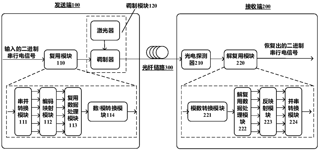
[0091] like figure 1 As shown, the optical fiber communication system between the time domain and the frequency domain provided by Embodiment 1 of the present invention includes a sending end 100 and a receiving end 200 , and the two perform information communication through an optical fiber link 300 .
[0092] The transmitting end 100 includes a multiplexing module 110 and a modulating module 120. The multiplexing module 110 converts the input serial binary electrical signal into N parallel electrical signals, and then converts it into a domain between the time domain and the frequency domain. To multiplex the electrical signal, the modulation module 120 modulates the multiplexed electrical signal onto an optical carrier to form a multiplexed optical signal, which is input into the optical fiber link 300 for transmission. N is a positive integer, which can be set according to the needs of the system.
[0093] The receiving end 200 includes a photodetector 210 and a demultipl...
specific Embodiment 2
[0100] Embodiment 2 of the present invention is to refine the structure of the signal multiplexing device, see figure 1 , the signal multiplexing device includes a serial-to-parallel conversion module 111 , a code mapping module 112 , a multiplexing data processing module 113 and a digital-to-analog conversion module 114 .
[0101] The serial-to-parallel conversion module 111 is used to divide the input serial electrical signal sequence into N groups, and convert it into N parallel electrical signals;
[0102]The encoding and mapping module 112 is configured to encode the above-mentioned N channels of parallel electrical signals, and map them into N channels of parallel high-order modulation signals, such as quadrature amplitude modulation and the like.
[0103] The multiplexing data processing module 113 is used to modulate the above-mentioned N channels of parallel high-order modulation signals onto subcarriers corresponding to the domain between the time domain and the freq...
specific Embodiment 3
[0106] Embodiment 3 of the present invention is the first implementation of the multiplexing data processing module, which is implemented in a traditional subcarrier multiplexing manner, such as Figure 4 As shown, its composition structure includes a time domain-frequency domain subcarrier generation module 1131 , N multipliers 1132 and an adder 1133 .
[0107] The time domain-frequency domain subcarrier generation module 1131 is used to generate N subcarriers on the domain between the time domain-frequency domain;
[0108] N multipliers 1132 multiply N channels of parallel high-order modulation signals with the above-mentioned subcarriers in the domain between the time domain and the frequency domain, thereby modulating to obtain N channels of time domain-frequency domain modulation signals;
[0109] The adder 1133 adds the above-mentioned N channels of time domain-frequency domain modulation signals, and multiplexes them into multiplexed electrical signals. The multiplexed...
PUM
 Abstract
Description
Claims
Application Information
 - R&D
- Intellectual Property
- Life Sciences
- Materials
- Tech Scout
- Unparalleled Data Quality
- Higher Quality Content
- 60% Fewer Hallucinations
Browse by: Latest US Patents, China's latest patents, Technical Efficacy Thesaurus, Application Domain, Technology Topic, Popular Technical Reports.
© 2025 PatSnap. All rights reserved.Legal|Privacy policy|Modern Slavery Act Transparency Statement|Sitemap|About US| Contact US: help@patsnap.com


