
Photoelectric module and control method thereof, imaging device, and electronic device

A technology for optoelectronic modules and imaging devices, which can be used in branch equipment, television, telephone communication, etc., and can solve the problem of high cost of electronic devices

Active Publication Date: 2018-12-14
GUANGDONG OPPO MOBILE TELECOMM CORP LTD
View PDF5 Cites 10 Cited by
  • Summary
  • Abstract
  • Description
  • Claims
  • Application Information

AI Technical Summary

Problems solved by technology

[0002] In order to obtain scene information and depth information, the electronic device generally needs to be equipped with an infrared camera module and a time of flight (Time Of Flight, TOF) camera module at the same time, which makes the cost of the electronic device relatively high

Method used


Image

  • Photoelectric module and control method thereof, imaging device, and electronic device
  • Photoelectric module and control method thereof, imaging device, and electronic device
  • Photoelectric module and control method thereof, imaging device, and electronic device

Examples


Embodiment Construction

[0024] Embodiments of the present application will be further described below in conjunction with the accompanying drawings. The same or similar reference numerals in the drawings represent the same or similar elements or elements having the same or similar functions throughout.

[0025] In addition, the embodiments of the present application described below in conjunction with the accompanying drawings are exemplary, and are only used to explain the embodiments of the present application, and should not be construed as limiting the present application.

[0026] In the present application, unless otherwise clearly specified and limited, a first feature being "on" or "under" a second feature may mean that the first and second features are in direct contact, or that the first and second features are indirect through an intermediary. touch. Moreover, "above", "above" and "above" the first feature on the second feature may mean that the first feature is directly above or obliquel...


PUM


Abstract

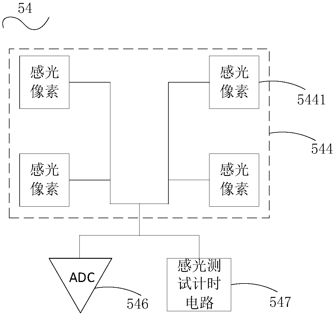
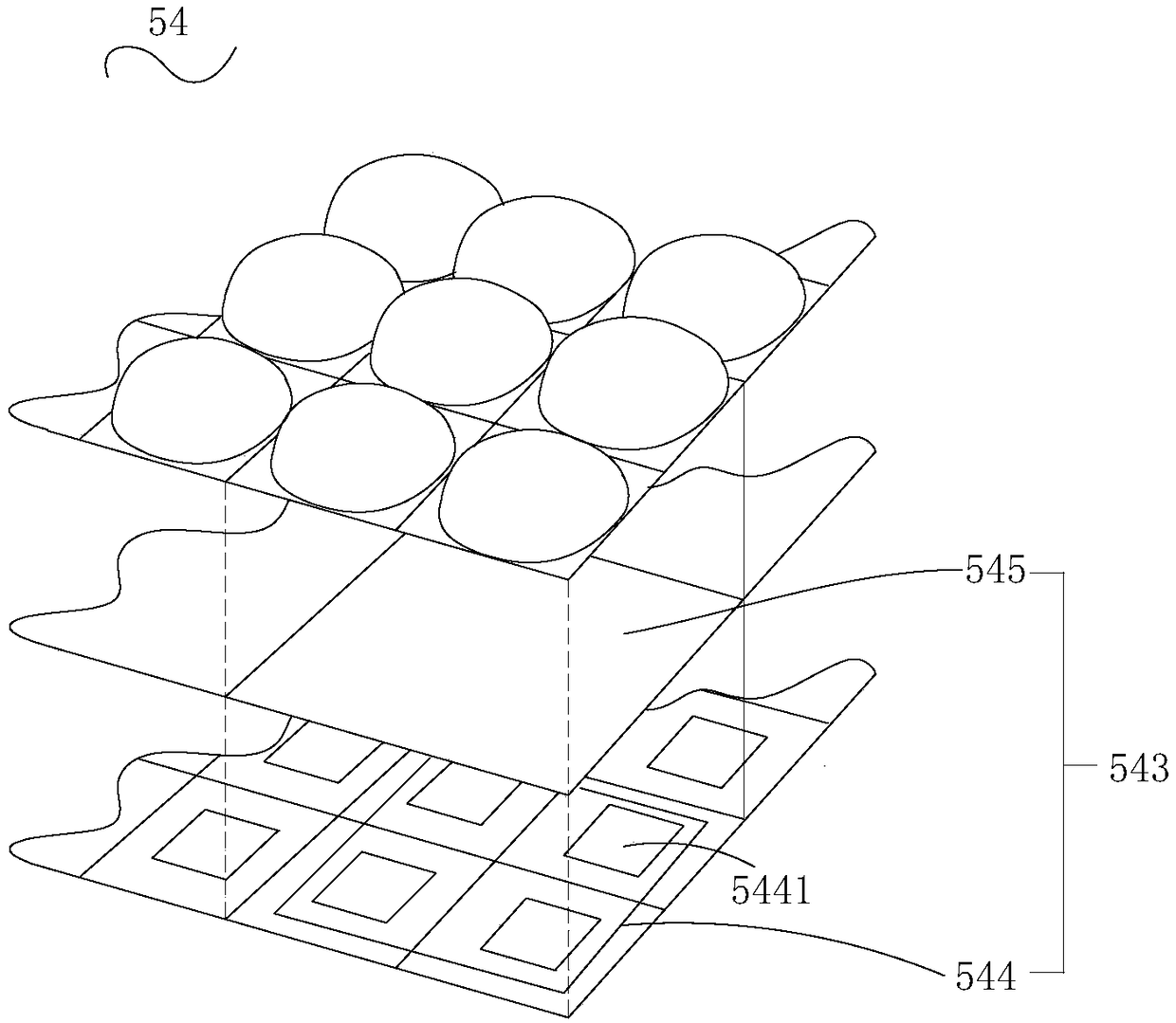
Disclosed are an optoelectronic module and a control method thereof, an imaging device and an electronic device. The photoelectric module includes an image sensor including an array of photosensitivepixel units and a filter for allowing light rays in a predetermined frequency band to pass therethrough. The photosensitive pixel unit array includes at least one photosensitive pixel unit, and the photosensitive pixel unit includes at least two photosensitive pixels. The photosensitive pixels belonging to the same photosensitive pixel unit share the same analog-to-digital converter and the same photosensitive test timing circuit. When scene information is formed, the photosensitive pixel outputs an electrical signal. When the depth information is formed, the photosensitive pixels belonging tothe same photosensitive pixel unit simultaneously output an electrical signal through an analog-to-digital converter and a photosensitive test timing circuit. The photoelectric module of the embodiment of the present application and the control method thereof, the imaging device and the electronic device acquire the scene information and the depth information through one image sensor, thereby avoiding the high cost of using two image sensors to acquire the scene information and the depth information respectively.

Description

technical field [0001] The present application relates to imaging technology, and more specifically, to an optoelectronic module, an imaging device, electronic equipment and a control method for the optoelectronic module. Background technique [0002] In order to obtain scene information and depth information, the electronic device generally needs to be equipped with an infrared camera module and a time of flight (Time Of Flight, TOF) camera module at the same time, which makes the cost of the electronic device relatively high. Contents of the invention [0003] Embodiments of the present application provide an imaging device, a method for controlling the imaging device, electronic equipment, and a computer-readable storage medium. [0004] The photoelectric module according to the embodiment of the present application includes an image sensor, and the image sensor includes a photosensitive pixel unit array and a filter. The optical filter is used to allow light of a pred...

Claims


Application Information

Patent Timeline
IPC IPC(8): H04N5/225H04M1/02
CPCH04M1/0264H04N23/50H04N23/57H04N23/55H04N23/54
Inventor 张学勇
Owner GUANGDONG OPPO MOBILE TELECOMM CORP LTD
Learn More