
Circular cleaning device for automobile brake pads

A technology for cleaning devices and brake pads, which is applied in the direction of cleaning methods using liquids, cleaning methods using tools, cleaning methods and utensils, etc., which can solve problems such as waste of water resources, potential safety hazards, and inability to ensure that brake pads are cleaned in place.

Active Publication Date: 2021-05-04
青岛日森机电有限公司
View PDF9 Cites 2 Cited by
  • Summary
  • Abstract
  • Description
  • Claims
  • Application Information

AI Technical Summary

Problems solved by technology

[0002] In the braking system of a car, brake pads are the most critical safety parts. The brake pads play a decisive role in the quality of all braking effects. Brake pads are generally composed of steel plates, adhesive insulation layers and friction blocks. Among them, friction The block is mainly composed of friction material and adhesive. When braking, it is squeezed on the brake disc or brake drum to generate friction, so as to achieve the purpose of vehicle deceleration and braking. Brake pads will produce a lot of impurities during the production process. Afterwards, various colloids or materials will be attached to its surface. The cleaning of brake pads is also a link in the production of brake pads. In the prior art, the cleaning of brake pads is mainly in the form of soaking and manual hand rubbing. , low efficiency, high labor costs, greatly affected by environmental factors, and even the adhesion between the brake pads may occur, making the cleaning impossible, and the cleaning of the brake pads cannot be guaranteed, and the impurities remaining on the surface of the brake pads affect the brake pads. function, resulting in safety hazards, and only one piece of brake pads can be cleaned at a time, the cleaning efficiency is low, and at the same time, it causes a lot of waste of water resources

Method used


Image

  • Circular cleaning device for automobile brake pads
  • Circular cleaning device for automobile brake pads
  • Circular cleaning device for automobile brake pads

Examples


Embodiment Construction

[0023] The technical solutions of the present invention will be further described below in conjunction with the accompanying drawings and specific embodiments.

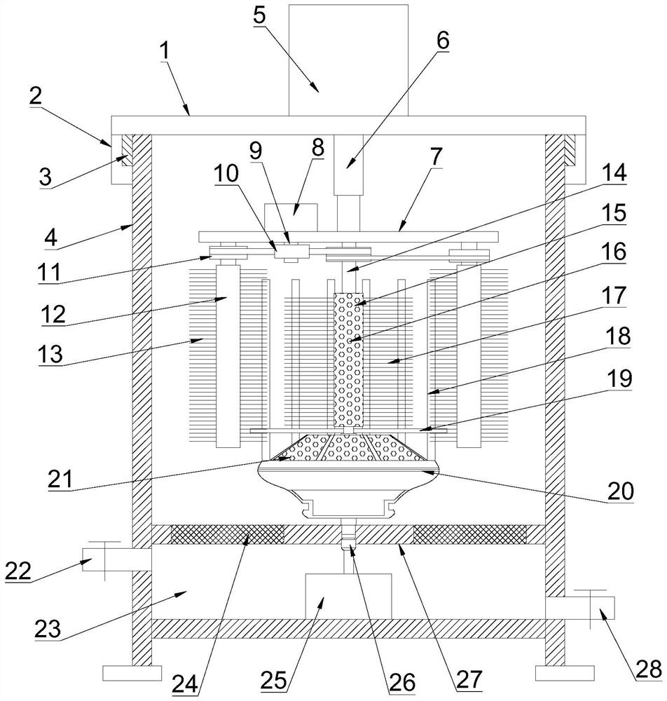
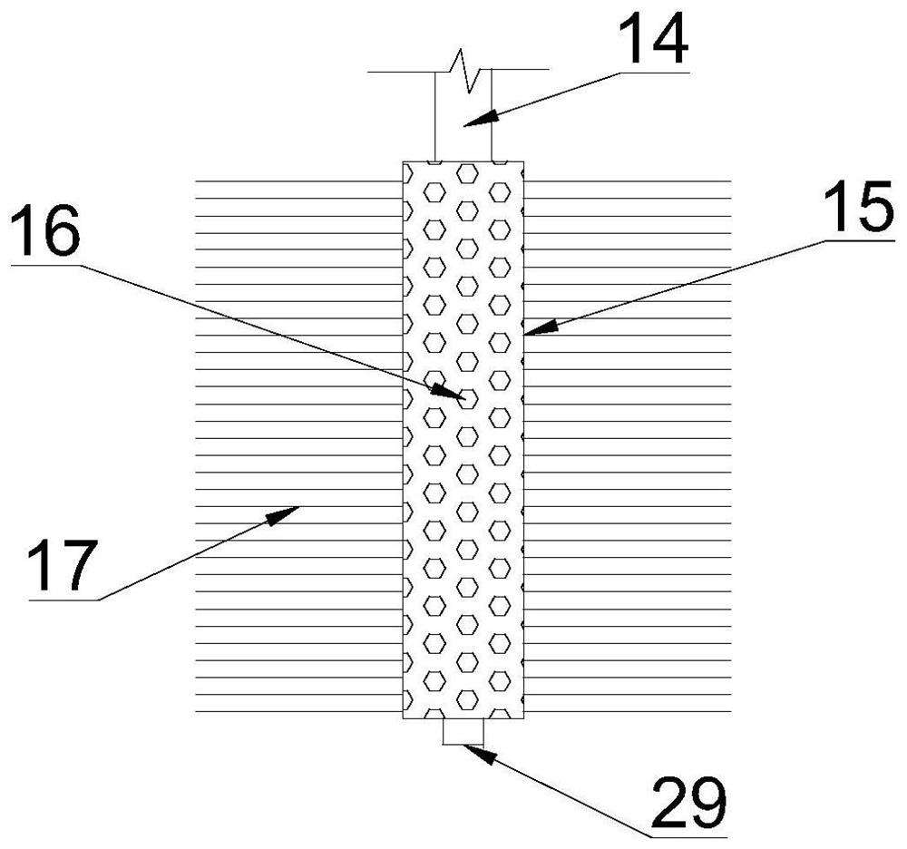
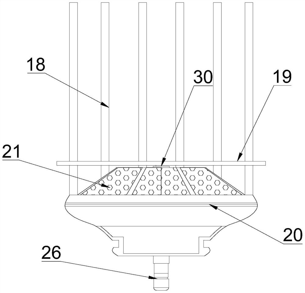
[0024] see Figure 1-4 , a circular cleaning device for automobile brake pads, comprising a cleaning cylinder cover 1, a cleaning cylinder body 4, a lifting plate 7, a drive sprocket 10, an outer cleaning roller 12, an inner cleaning roller 15, an assembly rod 18 and a cleaning seat 20, The cleaning cylinder cover 1 is installed on the top of the cleaning cylinder 4, and the cleaning cylinder cover 1 and the cleaning cylinder 4 are fastened and connected by the lock 2 and the lock tongue 3, the lock 2 is hinged on the outside of the cleaning cylinder cover 1, and the lock tongue 3 is fixed on the outer wall of the top end of the cleaning cylinder 4, and the lock catch 2 and the lock tongue 3 are fastened to realize the fixed connection between the two. The electric cylinder 5 is installed in the middle of the top end ...


PUM


Abstract

The invention discloses a circulating cleaning device for automobile brake pads, comprising a cleaning cylinder cover, a cleaning cylinder body, a lifting plate, a driving sprocket, an outer cleaning roller, an inner cleaning roller, an assembly rod and a cleaning seat. It is installed on the top of the cleaning cylinder. An electric cylinder is installed in the middle of the top of the cleaning cylinder cover. The electric cylinder is connected to the piston rod. The bottom end of the piston rod is connected to the lifting plate. There is a drive sprocket; the brake pads that can be placed in each layer are distributed above the assembly gasket in a circumferential direction, and the total number of cleaning car brake pads is multiplied by the number of stackable layers. The cleaning roller rotates at the same time to clean the outside and inside of the car brake pads, and the water spray holes and jet holes spray water, which is convenient for cleaning the car brake pads. After cleaning, the water circulates and saves water resources.

Description

technical field [0001] The invention relates to the field of automobile brake pad processing, more specifically, it relates to a circulation cleaning device for automobile brake pads. Background technique [0002] In the braking system of a car, brake pads are the most critical safety parts. The brake pads play a decisive role in the quality of all braking effects. Brake pads are generally composed of steel plates, adhesive insulation layers and friction blocks. Among them, friction The block is mainly composed of friction material and adhesive. When braking, it is squeezed on the brake disc or brake drum to generate friction, so as to achieve the purpose of vehicle deceleration and braking. Brake pads will produce a lot of impurities during the production process. Afterwards, various colloids or materials will be attached to its surface. The cleaning of brake pads is also a link in the production of brake pads. In the prior art, the cleaning of brake pads is mainly in the f...

Claims


Application Information

Patent Timeline
Patent Type & Authority Patents(China)
IPC IPC(8): B08B1/04B08B3/02B08B3/14
CPCB08B3/02B08B3/14B08B1/32
Inventor 潘勇
Owner 青岛日森机电有限公司
Learn More