Energy-saving high-efficiency reflow welding machine

A reflow soldering machine, high-efficiency technology, applied in welding equipment, auxiliary devices, metal processing and other directions, can solve the problems of inconvenient welding, affecting welding efficiency, heat and heat radiation transfer loss, etc., to improve the effect of welding and reduce heat loss. , the effect of improving work efficiency

Active Publication Date: 2018-12-18
ANHUI TECHN COLLEGE OF MECHANICAL & ELECTRICAL ENG
View PDF8 Cites 4 Cited by
  • Summary
  • Abstract
  • Description
  • Claims
  • Application Information

AI Technical Summary

Problems solved by technology

[0005] The object of the present invention is to provide an energy-saving and high-efficiency reflow soldering machine to solve the problem that in the process of using the existing reflow soldering machine proposed in the above-mentioned background technology, in order to maintain the temperature of the inside of the reflow soldering machine and the hot air, it is necessary to make the inside of the reflow soldering machine The heating circuit and the blower continue to work to generate high temperature, and due to the poor sealing at the inlet and outlet positions of the reflow soldering machine, most of the heat is lost through the heat radiation transfer between the air and the reflow soldering machine itself, and the heat is wasted, and the blower is blowing out the air. Afterwards, the wind energy is directly lost, and the gap between two adjacent blowers is not convenient for welding, which affects the welding efficiency.

Method used


Image

  • Energy-saving high-efficiency reflow welding machine
  • Energy-saving high-efficiency reflow welding machine
  • Energy-saving high-efficiency reflow welding machine

Examples


Embodiment Construction

[0022] The following will clearly and completely describe the technical solutions in the embodiments of the present invention with reference to the accompanying drawings in the embodiments of the present invention. Obviously, the described embodiments are only some, not all, embodiments of the present invention. Based on the embodiments of the present invention, all other embodiments obtained by persons of ordinary skill in the art without making creative efforts belong to the protection scope of the present invention.

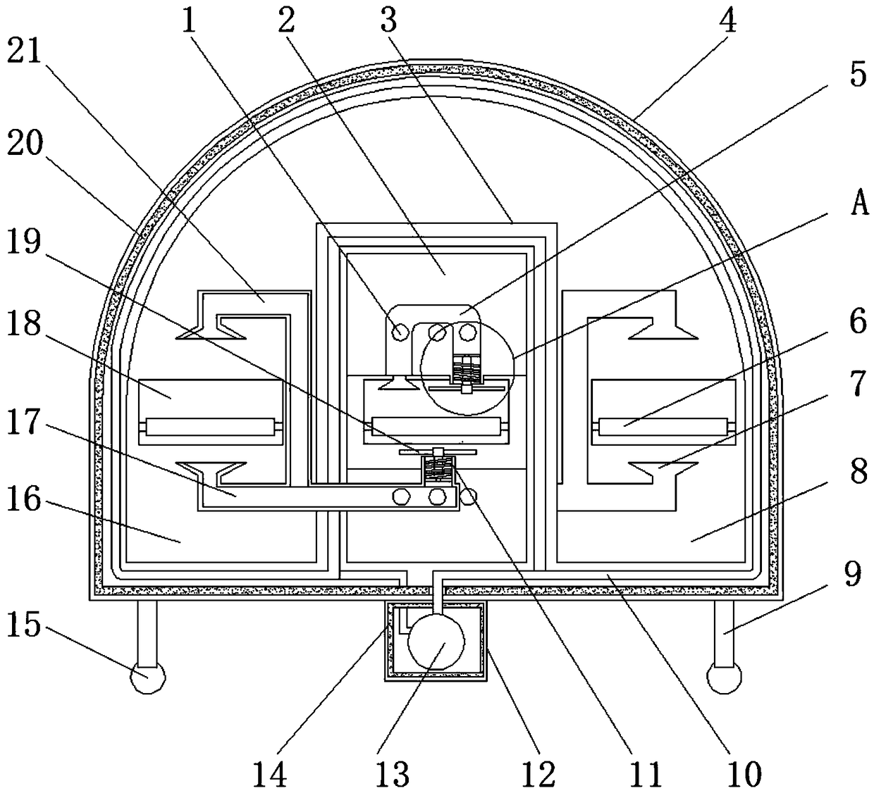
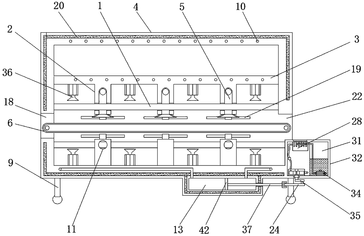
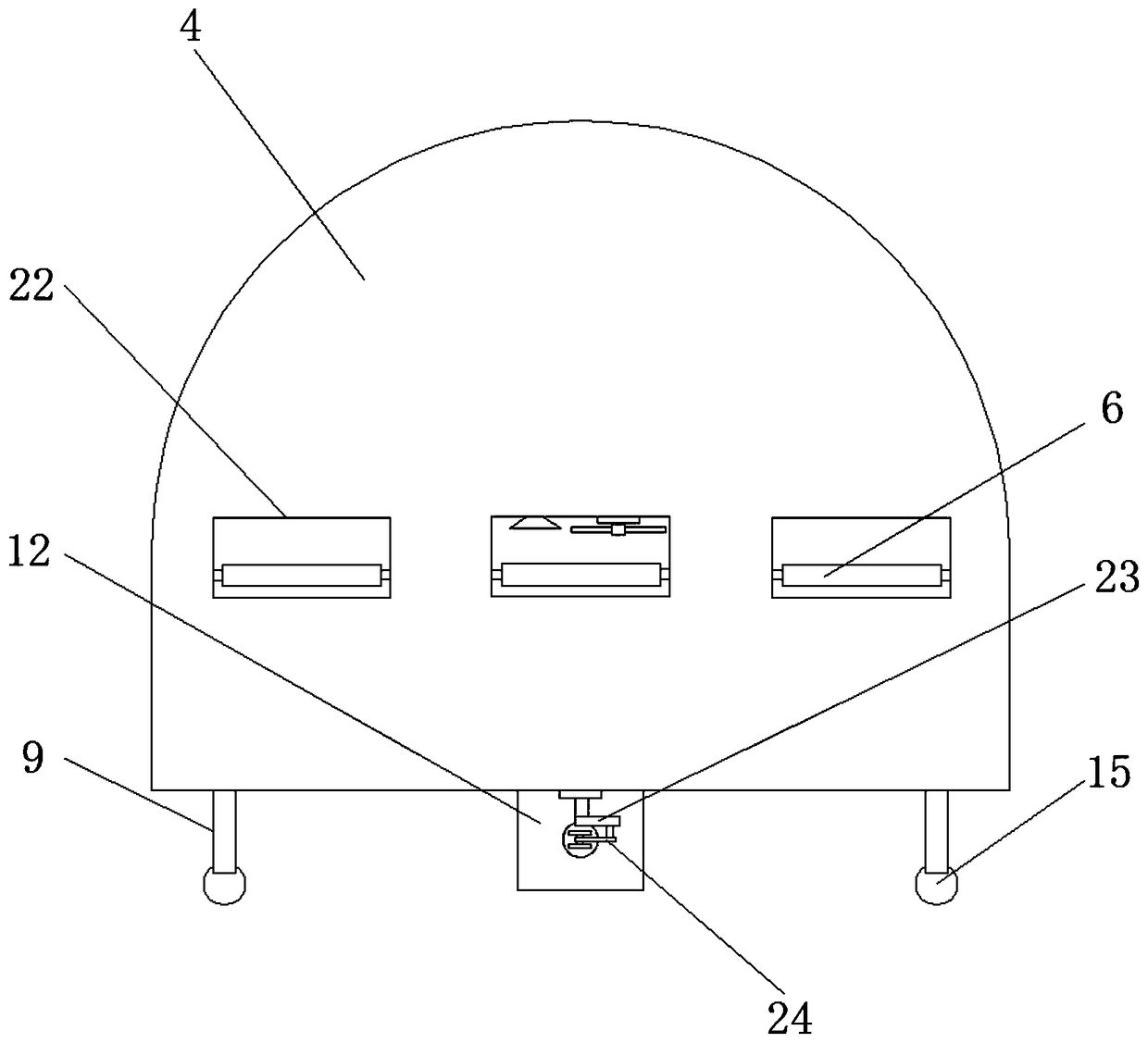
[0023] see Figure 1-5, an embodiment provided by the present invention: an energy-saving and high-efficiency reflow soldering machine, including a protective frame 3, a housing 4, a conveyor belt 6, a first auxiliary welding chamber 8, a circulation seat 12 and a second auxiliary welding chamber 16, the housing 4. A protective frame 3 is fixed at the middle position inside the protective frame 3. A first secondary welding chamber 8 is provided inside the shel...


PUM


Abstract

The invention discloses an energy-saving high-efficiency reflow welding machine. The energy-saving high-efficiency reflow welding machine comprises a protective frame, a shell, conveyor belts, a firstauxiliary welding chamber, a circulating seat and a second auxiliary welding chamber, wherein the protective frame is fixed at the middle position inside the shell; the first auxiliary welding chamber is arranged in the shell and on one side of the protective frame; the second auxiliary welding chamber is arranged in the shell and on the other side of the protective frame; and feed inlets are formed in one end, of the shell, at the positions of the second auxiliary welding chamber, the first auxiliary welding chamber and the protective frame. According to the energy-saving high-efficiency reflow welding machine, cooling plates are arranged at the parts, of the tops of fixed seats, at the positions of discharge outlets, heat-conducting fins extending into evaporation chambers are uniformlyarranged at the bottoms of the cooling plates, and liquid distribution pipes connected to the output ends of water pumps are extended into the evaporation chambers. Therefore, the heat-conducting fins can be used to conduct the temperature of the cooling plates conveniently and the temperature of hot air escaping from the discharge outlets can be collected, so that the heat loss is smaller; and cooling water is used to contact the heat-conducting fins to generate steam, which absorbs heat when evaporating, and workpieces moving to the positions of the discharge outlets are cooled, so as to improve the welding effect.

Description

technical field [0001] The invention relates to the technical field of electronic placement equipment, in particular to an energy-saving and high-efficiency reflow soldering machine. Background technique [0002] Due to the continuous miniaturization of electronic product PCB boards, chip components have appeared. The traditional welding method can no longer meet the needs. With the development of placement technology, the reflow soldering machine as a part of placement technology has also been developed accordingly. The application is becoming more and more extensive, and it has been applied in almost all electronic product fields. [0003] Reflow soldering technology is not new in the field of electronic manufacturing. The components on various boards used in our computers are soldered to the circuit board through this process. There is a heating circuit inside this device, which uses air or nitrogen After heating to a high enough temperature, it is blown to the circuit b...

Claims


Application Information

Patent Timeline
Patent Type & Authority Applications(China)
IPC IPC(8): B23K3/00B23K3/08
CPCB23K3/00B23K3/08B23K3/085
Inventor 王微柳砚
Owner ANHUI TECHN COLLEGE OF MECHANICAL & ELECTRICAL ENG
Why Eureka
Try Eureka