
Machining center for numerically controlled machine tool

A technology of machining centers and CNC machine tools, applied in metal processing equipment, metal processing machinery parts, manufacturing tools, etc., can solve the problems of inconvenient control and adjustment, unfavorable processing accuracy, and small adjustment range of CNC machine tool machining centers, etc., to achieve convenience The effect of daily maintenance, improving self-cleaning ability and reducing maintenance difficulty

Inactive Publication Date: 2018-12-18
滁州立特机械加工有限公司
View PDF1 Cites 0 Cited by
  • Summary
  • Abstract
  • Description
  • Claims
  • Application Information

AI Technical Summary

Problems solved by technology

This makes the original three-axis machine can not meet the requirements
[0003] After searching, a kind of CNC machine tool processing center is proposed in the document whose publication number is CN101633119A, including a machine tool and a controller for controlling the machine tool. The X-axis driving unit that drives the processing table to move back and forth, the CNC machine tool machining center has a small adjustment range, it is inconvenient to control the adjustment angle, and it is not conducive to improving the machining accuracy, so a CNC machine tool machining center is now proposed

Method used


Image

  • Machining center for numerically controlled machine tool
  • Machining center for numerically controlled machine tool
  • Machining center for numerically controlled machine tool

Examples


Embodiment Construction

[0018] The following will clearly and completely describe the technical solutions in the embodiments of the present invention with reference to the accompanying drawings in the embodiments of the present invention. Obviously, the described embodiments are only some, not all, embodiments of the present invention.

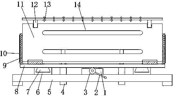
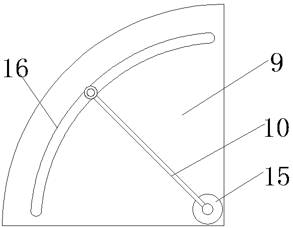
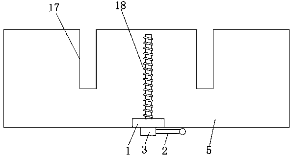
[0019] refer to Figure 1-3 , a CNC machine tool machining center, including a mounting base 5, metal grooves 6 are fixed on the outer walls on both sides of the top of the mounting base 5 by bolts, and sliding blocks 7 are clamped on the inner walls of the two metal grooves 6, and the two sliding blocks The top of 7 is fixed with a rectangular frame 8 by bolts, the outer wall of the top side of the rectangular frame 8 is hinged with a mounting plate 11, and the outer wall of the mounting plate 11 close to the rectangular frame 8 is hinged with two pneumatic telescopic rods 4, and the two pneumatic telescopic rods 4 The side walls are movably connected with the inner...


PUM


Abstract

The invention discloses a machining center for a numerically controlled machine tool. The machining center comprises a mounting seat, wherein metal groove strips are fixed to the outer walls of two sides of the top end of the mounting seat by bolts, and sliding blocks are connected to the inner walls of the two metal groove strips in a clamped mode correspondingly, and rectangular frames are fixedto the top ends of the two sliding blocks by bolts. A mounting plate is hinged to the outer wall of one side of the top end of the rectangular frames, and two pneumatic telescopic rods are hinged tothe outer wall of the side, close to the rectangular frames, of the mounting plate, the side walls of the two pneumatic telescopic rods are movably connected with the inner walls of the rectangular frames respectively, and two strip-shaped notches are formed in the outer wall of the top end of the mounting seat, and the two pneumatic telescopic rods penetrate through the two strip-shaped notches respectively. The machining center for the numerically controlled machine tools convenient to adjust an angle of the mounting plate, convenient to process workpieces from different angles, simple to operate, large adjustment range, more labor saving, convenient to control and adjust the angle, more intelligent, conducive to improve the machining accuracy, enriches the function of the p machining center, convenient for daily maintenance, reduces the maintenance difficulty, and is convenient to clean.

Description

technical field [0001] The invention relates to the technical field of numerical control machine tool processing, in particular to a numerical control machine tool processing center. Background technique [0002] CNC (Numerical Control Machine Tool) is the abbreviation of computer numerical control machine tool, which is an automatic machine tool equipped with a program control system. The control system can logically process and decode programs with control codes or other symbolic instructions, so as to make the machine tool move and process parts. CNC machining center is a highly automated multifunctional CNC machine tool with tool magazine and automatic tool changer. After the workpiece is clamped once on the CNC machining center, it can complete multiple processes on more than two surfaces, and has multiple tool changing or tool selection functions, thereby greatly improving production efficiency. Machining centers can be divided into three-axis, four-axis and five-axi...

Claims


Application Information

Patent Timeline
IPC IPC(8): B23Q1/25B23Q3/04B23Q11/00
CPCB23Q1/25B23Q3/04B23Q11/005
Inventor 李阳
Owner 滁州立特机械加工有限公司
Learn More