Steel plate polishing device for processing metal product

A technology of metal products and polishing devices, which is applied in metal processing equipment, manufacturing tools, grinding/polishing equipment, etc., can solve the problems of limited polishing range, manual adjustment, and reduced polishing operation efficiency, so as to increase the efficiency of grinding and polishing. Range, guaranteed polishing effect, easy and fast lifting operation

Active Publication Date: 2018-12-18
兴化市新泰铸钢有限公司
View PDF5 Cites 21 Cited by
  • Summary
  • Abstract
  • Description
  • Claims
  • Application Information

AI Technical Summary

Problems solved by technology

[0003] In the production and processing of metal products, steel plates are widely used as raw materials. Before further processing and use, the surface of the steel plate needs to be polished and polished to achieve a smooth surface of the steel plate. The current steel plate polishing device has a relatively limited range of polishing and polishing. , requires continuous manual adjustment, and the polishing operation efficiency is greatly reduced. Therefore, a steel plate polishing device for metal product processing is now provided to solve the above technical problems

Method used


Image

  • Steel plate polishing device for processing metal product
  • Steel plate polishing device for processing metal product
  • Steel plate polishing device for processing metal product

Examples


Embodiment 1

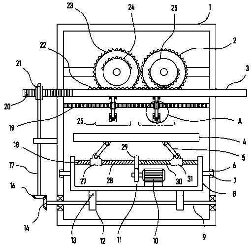
[0021] see Figure 1-3 , a steel plate polishing device for metal product processing, including a support frame 1, a bearing frame 8 is arranged in the support frame 1, a support plate 4 is installed on the support frame 8, and the set support plate 4 is used to place the steel plate to be polished.

[0022] The support frame 1 is horizontally slidable and is provided with a slide plate 3 , the upper rack 22 is fixed on the slide plate 3 , and the drive gear I2 and the drive gear II23 which are connected to each other in the support frame 1 are rotatably provided, and the drive gear I2 and the drive gear II23 An incomplete gear I24 and an incomplete gear II25 are respectively coaxially fixed on the top, and the upper rack 22 meshes with the incomplete gear I24 or the incomplete gear II25.

[0023] The transmission gear II23 is connected with a driving motor, the transmission gear II23 is coaxially fixed with the output shaft of the driving motor, the transmission gear II23 dri...

Embodiment 2

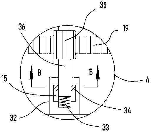
[0028] On the basis of Embodiment 1, in addition, a transmission rack 20 is fixed on the slide plate 3, and a cylindrical spur gear I21 engaged with it is rotatably provided on the transmission rack 20, and a rotating shaft 17 is coaxially fixed on the cylindrical spur gear I21. The lower end of the rotating shaft 17 is coaxially fixed with a driving bevel gear 16, the bottom of the driving bevel gear 16 is provided with a driven bevel gear 14 meshing with it, and the driven bevel gear 14 is coaxially fixed with a driven shaft 9 located below the bearing frame 8. A connecting gear 12 is sheathed on the driven shaft 9 , and a connecting rack 13 meshing with the connecting gear 12 is fixedly mounted on the bottom of the bearing frame 8 .

[0029] The slide plate 3 and the transmission rack 20 reciprocate left and right, and the transmission rack 20 drives the rotating shaft 17 to alternately rotate counterclockwise through the cylindrical spur gear 121 meshed with it, and then re...

Embodiment 3

[0032] On the basis of Embodiment 2, in addition, the bearing frame 8 is provided with an adjustment shaft 18 in a rotating manner, and the surface of the adjustment shaft 18 is tapped with a first external thread 28 and a second external thread 30 with symmetrical positions and opposite rotation directions. The shaft 18 is sleeved with a threaded sleeve I27 threaded with the first external thread 28 and a threaded sleeve II31 threaded with the second external thread 30, and the threaded sleeve I27 and the threaded sleeve II31 are hinged to the support plate 4 A support rod 5 is arranged, and the upper end of the support rod 5 is hinged on the lower surface of the support plate 4 .

[0033] Further, the forward and reverse motor 10 is fixedly installed in the bearing frame 8, the output shaft of the forward and reverse motor 10 is fixedly installed with the drive gear 11, and the surface of the adjustment shaft 18 is sleeved and fixedly installed with a slave gear meshed with t...


PUM


Abstract

The invention discloses a steel plate polishing device for processing a metal product, and relates to the technical field of metal product processing machinery. The steel plate polishing device includes a supporting frame, a bearing frame is arranged in the supporting frame, a supporting plate is mounted on the bearing frame, and a sliding plate is arranged on the supporting frame in a horizontalsliding and penetrating mode; and a first incomplete gear and a second incomplete gear are fixed on a first transmission gear and a second transmission gear coaxially, and a limiting rack meshed and connected with a second cylindrical straight gear is fixedly mounted in the supporting frame. According to the steel plate polishing device, a steel plate placed on a supporting plate can be ground andpolished through the left and right reciprocating motion and rotation of a polishing disc, meanwhile, the supporting plate can reciprocate back and forth, the range of grinding and polishing of the steel plate is greatly increased, the polishing efficiency is greatly improved, the lifting operation of the supporting plate is simple and fast, the fact that the steel plate on the supporting plate keeps contact with the polishing disc is ensured, meanwhile, through the limit spring elastic action, the sufficient pressure of the polishing disc on the steel plate is achieved, and the polishing effect of the steel plate is ensured.

Description

technical field [0001] The invention relates to the technical field of luggage processing machinery, in particular to a steel plate polishing device for processing metal products. Background technique [0002] The metal product industry includes structural metal product manufacturing, metal tool manufacturing, container and metal packaging container manufacturing, stainless steel and similar daily-use metal product manufacturing, etc. With the progress of society and the development of science and technology, metal products are used more and more widely in various fields of industry, agriculture and people's life, and they also create more and more value for society. The metal products industry also encountered some difficulties in the development process, such as single technology, low technical level, lack of advanced equipment, shortage of talents, etc., which restricted the development of the metal products industry. To this end, the development of China's metal product...

Claims


Application Information

Patent Timeline
Patent Type & Authority Applications(China)
IPC IPC(8): B24B29/02B24B41/06B24B41/02
CPCB24B29/02B24B41/02B24B41/068
Inventor 谢中守
Owner 兴化市新泰铸钢有限公司
Why Eureka
Try Eureka