Portable charger

A charger and portable technology, applied in electric traction, electric vehicles, power electronics modification and other directions, can solve the problems of a small number of piles, set in a fixed location, unable to realize emergency charging, etc., to save floor space, reduce Effects of load and dead weight, improved mobility and flexibility

Active Publication Date: 2018-12-18
AIA ELECTRIC PINGHU CO LTD
View PDF10 Cites 3 Cited by
  • Summary
  • Abstract
  • Description
  • Claims
  • Application Information

AI Technical Summary

Problems solved by technology

[0005] It is worth noting that although the existing charging piles are in the stage of rapid popularization, there are still problems such as the small number of piles and fixed piles, the piles need to be set at fixed locations, and emergency charging cannot be realized to varying degrees.

Method used


Image

  • Portable charger
  • Portable charger
  • Portable charger

Examples


Embodiment Construction

[0045] The present invention discloses a portable charger. The specific implementation of the present invention will be further described below in conjunction with preferred embodiments.

[0046] See attached Figure 1 to Figure 13B , Figure 1 to Figure 13B The external / internal structure of the portable charger are respectively shown.

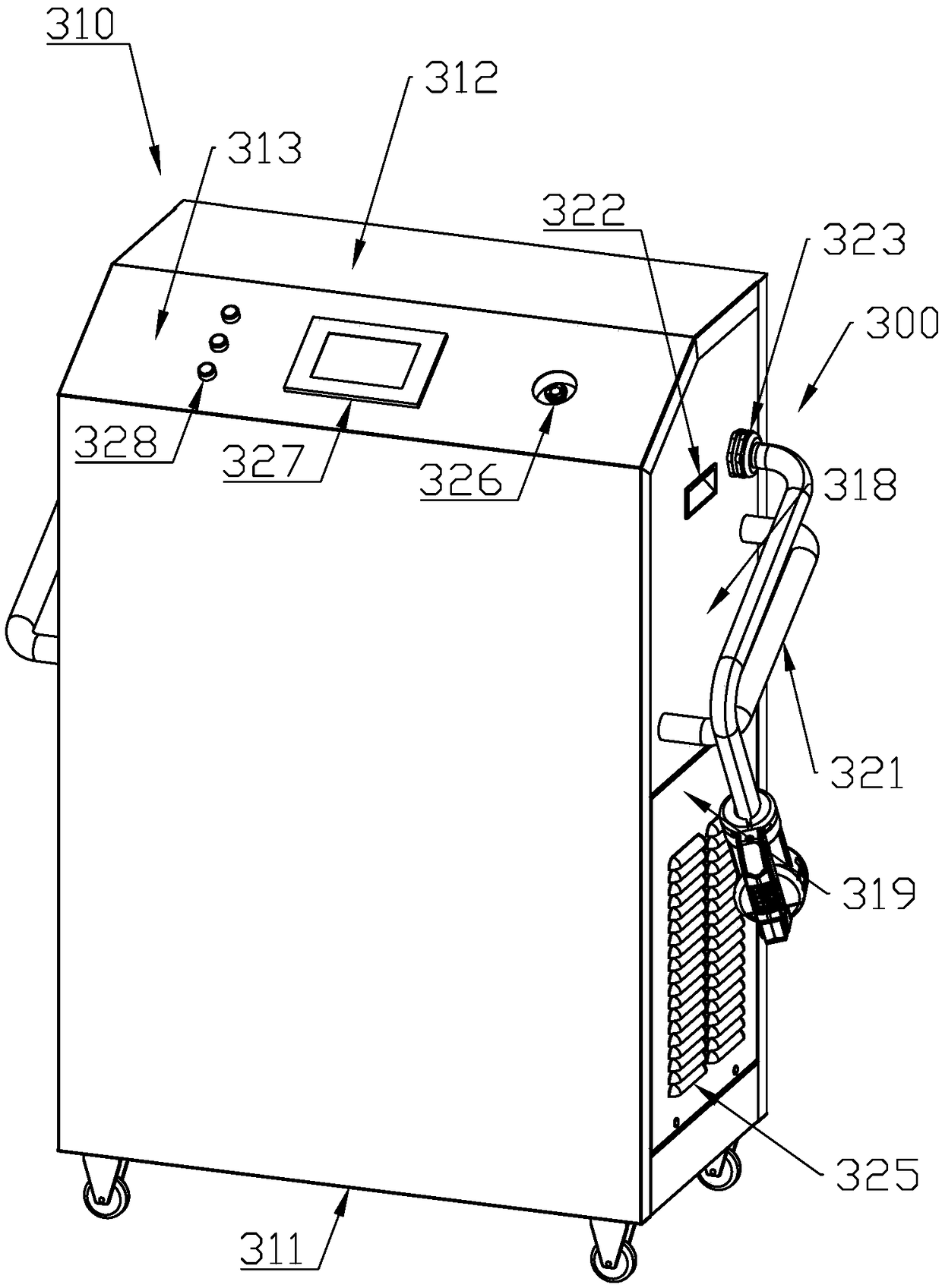
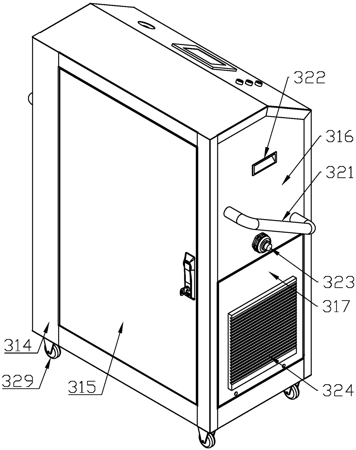
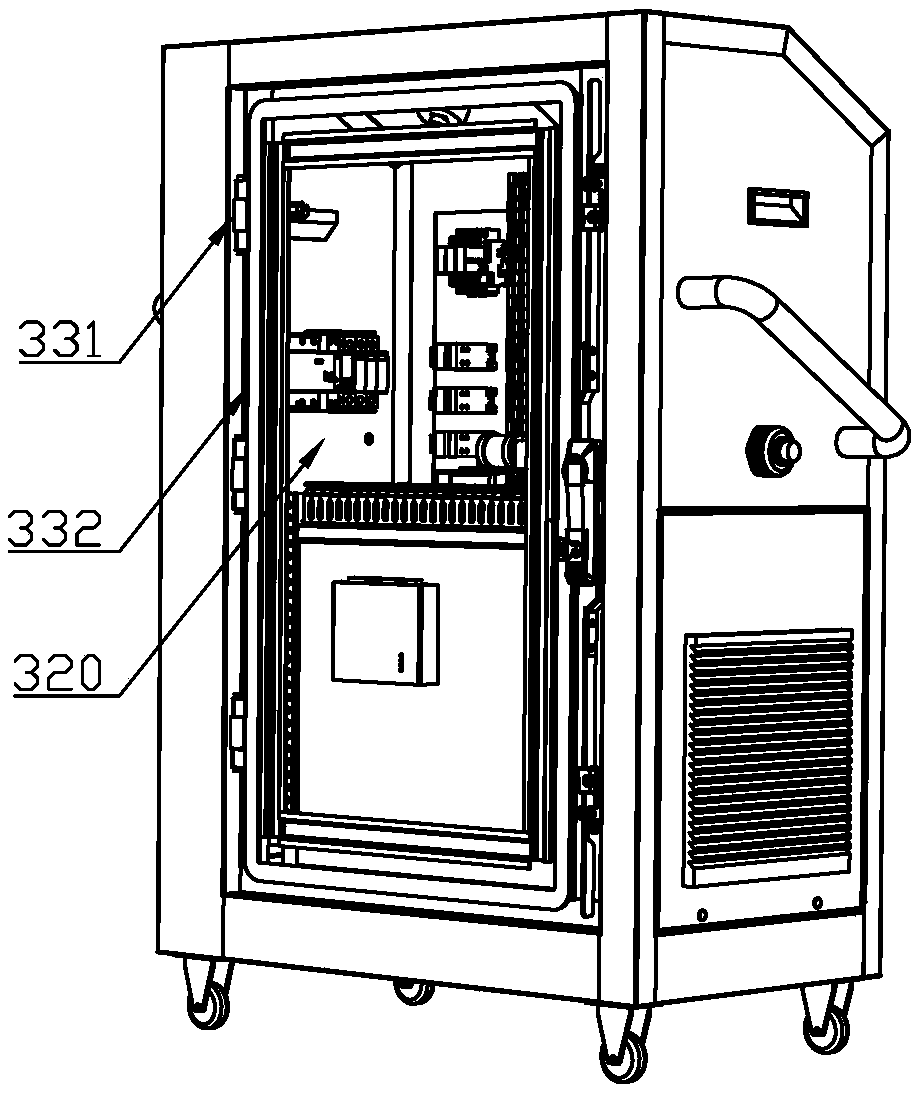
[0047] Preferably, the portable charger includes a supporting mechanism 300, a ventilation module 400 and a DC output module 200 built into the supporting mechanism 300, and the DC output module 200 is located above the ventilation module 400, wherein:

[0048] The supporting mechanism 300 includes a main frame 310, wherein:

[0049] The main body frame 310 includes a rear plate 314 and a front shell formed of a front plate 311, a top plate 312, an inclined top plate 313 and a bottom plate (not shown) integrally formed. The rear plate 314 is welded and connected to the front shell. The rear panel 314 is hinged with the rear door panel 315 through a...


PUM


Abstract

The invention discloses a portable charger, comprising a support mechanism, a ventilation module and a direct current output module built in the support mechanism. The support mechanism includes a body frame. The ventilation module comprises a ventilation module side plate, a ventilation module front cover plate, a ventilation module rear cover plate and at least one ventilation plug assembly. A portable charger is disclosed in which side plate restraints located on both sides and at the same relative height divide the receiving chamber into vent plug assembly slots consistent with the numberof vent plug assemblies to quickly plug or unload the vent plug assemblies as required. While meeting ventilation and heat dissipation requirements, minimize the load and dead weight of portable chargers. The main frame is in a flat stereoscopic configuration, which saves the floor area of the portable charger as much as possible, makes full use of the stereoscopic space, and improves the mobilityand flexibility of the portable charger.

Description

Technical field [0001] The invention belongs to the technical field of portable charging equipment, and specifically relates to a portable charging machine. Background technique [0002] At present, as the exploitation of fossil fuels such as coal and petroleum continues to increase, there is an urgent need to find renewable energy sources. Among them, diesel locomotives represented by automobiles are extremely widely used worldwide. The total amount of fossil energy consumed by fuel vehicles every year is amazing. At the same time, due to exhaust gas and other reasons, air pollution is inevitably caused. According to statistics, automobile exhaust has become one of the three major air pollution sources in my country. [0003] According to the mainstream trend of the development and evolution of the automobile industry, new energy vehicles, especially pure electric vehicles or plug-in hybrid vehicles, occupy the mainstream market share. [0004] It is worth noting that it only ta...

Claims


Application Information

Patent Timeline
Patent Type & Authority Applications(China)
IPC IPC(8): B60L11/18H05K7/20
CPCH05K7/20909Y02T10/70Y02T10/7072
Inventor 王帅田占军王鹏王德虎李杰庾寅翀
Owner AIA ELECTRIC PINGHU CO LTD
Why Eureka
Try Eureka