Device of improving quenching and cooling

A quenching tank and shunt layer technology, used in quenching devices, heat treatment equipment, furnaces, etc., can solve the problems of unqualified parts structure, different cooling liquid amounts, and different cooling effects of parts, etc., to achieve strong applicability, uniform and effective cooling. , The effect of improving the quality of parts

Active Publication Date: 2018-12-18
ZHEJIANG 81 PRECISION MACHINERY CO LTD +1
View PDF13 Cites 0 Cited by
  • Summary
  • Abstract
  • Description
  • Claims
  • Application Information

AI Technical Summary

Problems solved by technology

[0002] In the production of box-type multi-purpose furnace, when the parts are quenched and cooled, uneven cooling leads to large differences in structure, which has always been a problem that plagues the industry. Too fast cooling leads to deformation or cracking of parts, and too slow cooling leads to unqualified parts.
Especially in the box-type multi-purpose furnace, the phenomenon is more obvious, because the parts are used, quenching from top to bottom, the oil circulation uses the agitator deflector to divert the flow into the quenching tank, resulting in different coolant volumes in each section after quenching , resulting in a difference in the cooling effect of the parts

Method used


Image

  • Device of improving quenching and cooling
  • Device of improving quenching and cooling

Examples


Embodiment Construction

[0020] The present invention will be described in further detail below in conjunction with the accompanying drawings.

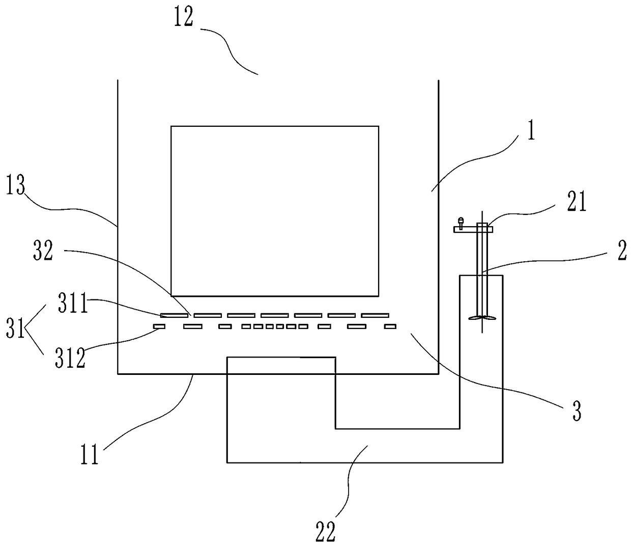
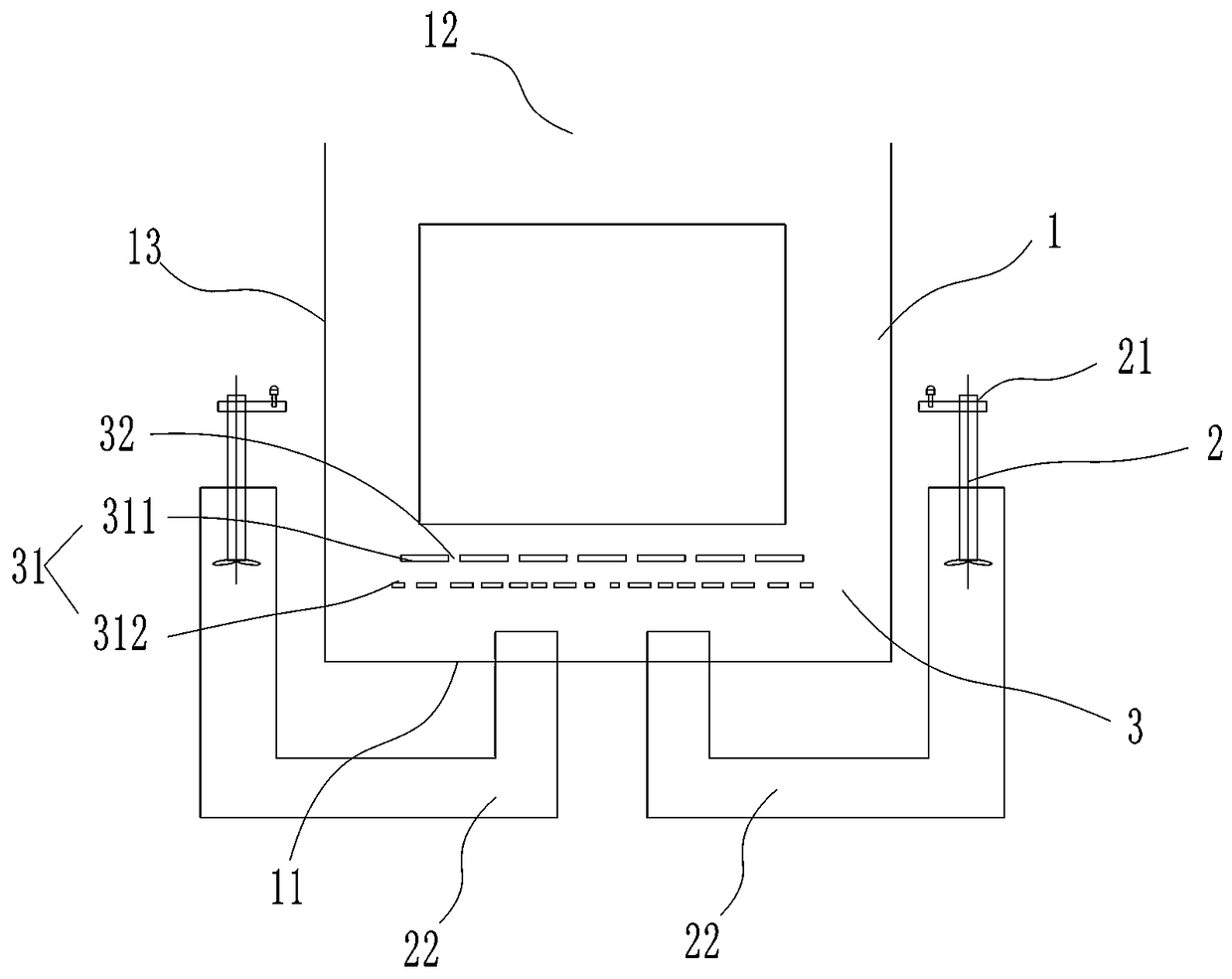
[0021] Such as figure 1 and 2 As shown, an anti-glare narrow-beam LED lamp includes a quenching tank 1 and a power output device 2 connected to the quenching tank 1. The quenching tank 1 is at least provided with a flow distribution device 3, and the quenching tank 1 includes a bottom 11. An open top 12 and a side wall 13 connecting the bottom 11 and the top 12 , the flow distribution device 3 is connected to the side wall 13 .

[0022] In this embodiment, the diversion device 3 includes a diversion layer 31 and a plurality of diversion slits 32 provided on the diversion layer 31, the plurality of diversion slits 32 are arranged parallel to each other, and the diversion slits 32 are It is the channel opening of the quenching coolant, and the quenching cooling enters the quenching tank 1 from the power output device 2 and must pass through the distribution d...


PUM


Abstract

The invention provides a device of improving quenching and cooling. The device of improving quenching and cooling is designed for solving the technical problems that when a part is quenched and cooled, the organization difference is large due to the fact that cooling is not uniform, the part deforms or is cracked due to the fact that cooling is too fast, and the organization of the part is not qualified due to the fact that cooling is too slow. The device of improving quenching and cooling comprises a quenching tank and a power output device, wherein the power output device is connected with the quenching tank. The quenching tank at least comprises a flow distribution facility. The quenching tank comprises a bottom, an open top and a side wall, wherein the side wall is connected with the bottom and the top. The flow distribution facility is connected with the side wall. An oil flow distribution device, namely a flow guide seam, is added in a stirring flow guide opening formed in the bottom of an existing facility, the flow of quenching liquid in various regions is controlled according to the seam to achieve the purpose that cooling of the part in the quenching process is more uniform and more effective, and therefore the quality of the part is improved.

Description

technical field [0001] The invention relates to the technical field of metal heat treatment design, in particular to a device for improving quenching and cooling. Background technique [0002] In the production of box-type multi-purpose furnace, when parts are quenched and cooled, uneven cooling leads to large differences in structure, which has always been a problem that plagues the industry. Too fast cooling will cause deformation or cracking of parts, and too slow cooling will lead to unqualified parts. Especially in the box-type multi-purpose furnace, the phenomenon is more obvious, because the parts are used, quenching from top to bottom, the oil circulation uses the agitator deflector to divert the flow into the quenching tank, resulting in different coolant volumes in each section after quenching , resulting in a difference in the cooling effect of the parts. By adding an oil diversion device (divergence slot) at the bottom of the original equipment and at the stirri...

Claims


Application Information

Patent Timeline
Patent Type & Authority Applications(China)
IPC IPC(8): C21D1/64C21D9/00
CPCC21D1/64C21D9/0062Y02P10/20
Inventor 曹海军张春宝陈云汪凤文
Owner ZHEJIANG 81 PRECISION MACHINERY CO LTD
Why Eureka
Try Eureka