Forcible air cooling internal combustion engine

An air cooling, internal combustion engine technology, applied in the direction of engine cooling, mechanical equipment, engine components, etc., can solve the problem of difficult to use cooling internal combustion engine and so on

Active Publication Date: 2010-08-11
HONDA MOTOR CO LTD
View PDF2 Cites 0 Cited by
  • Summary
  • Abstract
  • Description
  • Claims
  • Application Information

AI Technical Summary

Problems solved by technology

[0004] For example, an internal combustion engine mounted on a scooter is placed inside a main body cover that covers the front and sides of the internal combustion engine, making it difficult to cool the internal combustion engine with the flow of air generated by operating the vehicle

Method used


Image

  • Forcible air cooling internal combustion engine
  • Forcible air cooling internal combustion engine
  • Forcible air cooling internal combustion engine

Examples


Embodiment Construction

[0064] Hereinafter, referring to the drawings, a mode of the present invention will be described according to one embodiment of the present invention.

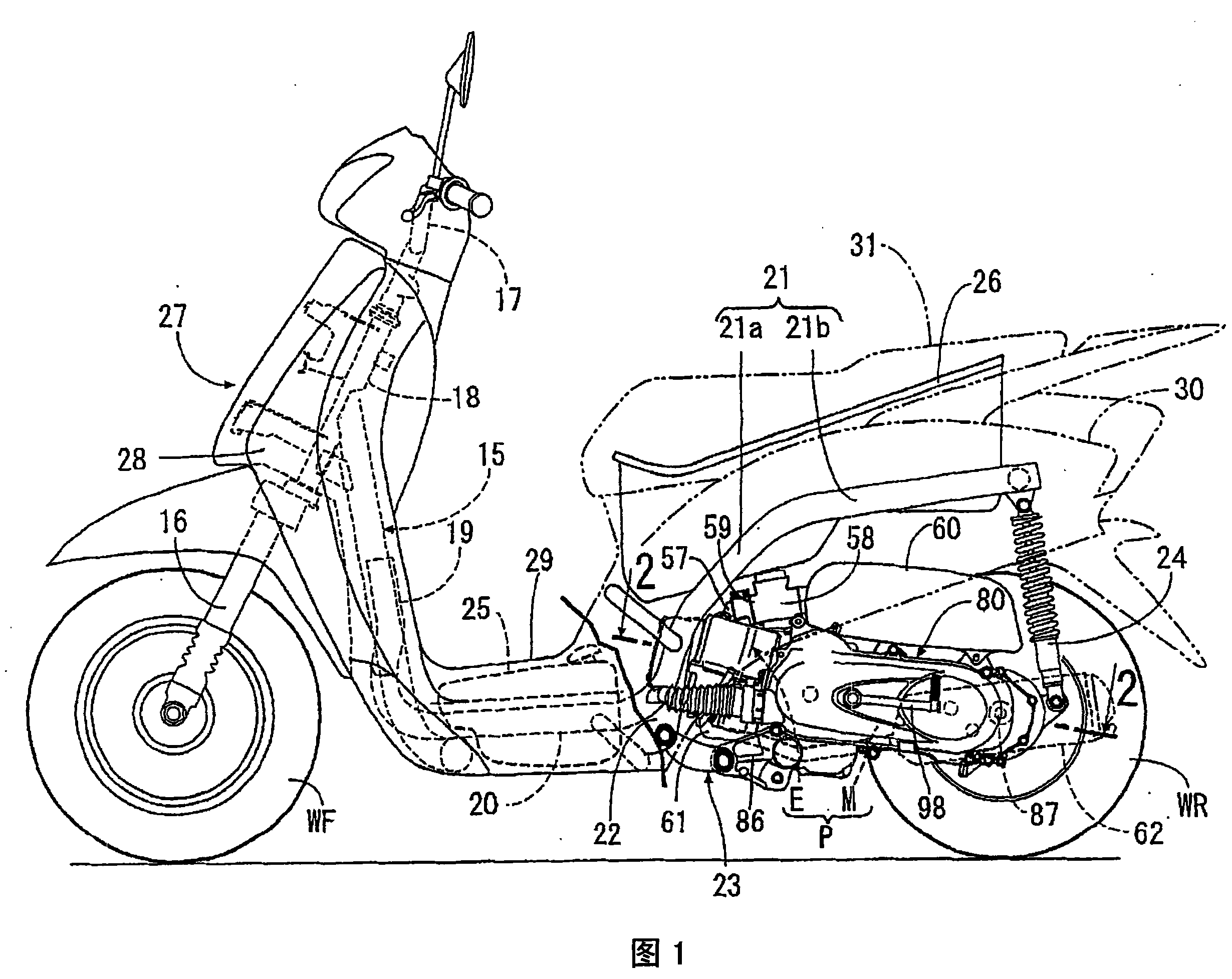
[0065] As shown in FIG. 1 , the body frame 15 of the scooter includes a head pipe 18 that steerably receives a front fork 16 to which a front wheel WF is journalled with a steering handle 17 . A down tube 19 extends rearward and downward from the head pipe 18 . A pair of left and right lower frame tubes 20 extend rearward, and the pair of left and right lower frame tubes 20 have front ends respectively fixed to lower sides of the down tube 19 . A pair of left and right rear frame tubes 21 is integrally connected to the rear end of the lower frame tube 20 . Each rear frame tube 21 includes a rising frame portion 21a and an upper frame portion 21b, the rising frame portion 21a extends backward and upward from the rear end of each lower frame tube 20, and the upper frame portion 21b extends from the rear end of the rising frame ...


PUM


Abstract

The present invention provides an internal combustion engine having forced air cooling which effectively cools spark plug, wherein, the cooling fin is covered by a shielding cover from a projecting cylinder body and a cylinder cover, so as to form a cooling air passage between the shielding cover, the cylinder body and the cylinder cover. A cooling fan used for ventilating the cooling air absorbed from the shielding cover exterior to the cooling air passage is relative to a crank and connected to the crank. An air outlet used for draining the cooling air inflowing the cooling air passage to the exterior is formed to the shielding cover. An incision space is formed to one part of the cylinder body periphery by partly shortening or removing the cooling fin projecting from the periphery of the cylinder body. A first projecting and a second projecting are formed on the shielding cover, the first projecting projects inwards along the incision space, the second projecting attaching to the spark plug on one side of the cylinder cover is located in the position between the second projecting and the first projecting which projects inwards.

Description

technical field [0001] The invention relates to an internal combustion engine with forced air cooling, in which a cylinder block is connected to a crankcase, which rotatably houses a crankshaft, and from which cooling fins protrude. A cylinder head is connected to the cylinder block and has an ignition plug attached thereto. The shroud forms a cooling air passage between the shroud, the cylinder block, and the cylinder head. A cooling fan is provided for ventilating cooling air drawn in from outside the shroud to the cooling air passage, the cooling fan being associated with and connected to the crankshaft. The air outlet is provided to discharge the cooling air flowing through the cooling air passage, which is formed to the shield cover, to the outside. Background technique [0002] Japanese Patent Document JP-A No. H7-332084 discloses an internal combustion engine with forced air cooling. In this internal combustion engine with forced air cooling, an air outlet is provi...

Claims


Application Information

Patent Timeline
Patent Type & Authority Patents(China)
IPC IPC(8): F01P5/06B62J99/00
Inventor 土屋粒二堤英克高室真人沼崎芳美
Owner HONDA MOTOR CO LTD
Why Eureka
Try Eureka