Ion sputtering instrument with adjustable rotating sample rack

A technology of ion sputtering and sample holder, which is applied in the field of ion sputtering, can solve the problems of reduced service life, easy slip damage, component aging, etc., and achieve the effect of avoiding slip damage and aging

Pending Publication Date: 2018-12-18
JIANGSU NEPES SEMICON
View PDF0 Cites 0 Cited by
  • Summary
  • Abstract
  • Description
  • Claims
  • Application Information

AI Technical Summary

Problems solved by technology

[0004] The purpose of the present invention is to provide an ion sputtering instrument with an adjustable rotating sample holder to solve the problem that the sample detection cylinder at the top of the existing ion sputtering instrument proposed in the above background technology cannot be connected with the bottom box of the ion sputtering instrument. Fixed, the sample detection cylinder is easy to slip and damage after being touched, and when the ion sputtering instrument is working, the heat generated inside the ion sputtering instrument cannot be dissipated quickly, which will easily cause the components inside the ion sputtering instrument to be overheated and aging, reducing The problem of service life

Method used


Image

  • Ion sputtering instrument with adjustable rotating sample rack
  • Ion sputtering instrument with adjustable rotating sample rack
  • Ion sputtering instrument with adjustable rotating sample rack

Examples


Embodiment Construction

[0016] The following will clearly and completely describe the technical solutions in the embodiments of the present invention with reference to the accompanying drawings in the embodiments of the present invention. Obviously, the described embodiments are only some of the embodiments of the present invention, not all of them. Based on the embodiments of the present invention, all other embodiments obtained by persons of ordinary skill in the art without making creative efforts belong to the protection scope of the present invention.

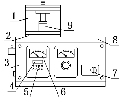
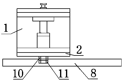
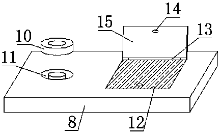
[0017] see figure 1 , figure 2 , image 3 and Figure 4 , the present invention provides a technical solution: an ion sputtering instrument with an adjustable rotating sample holder, including a sample holder 9, a sample holder outer shield 1 and an ion sputtering instrument bottom box 3, and also includes a fixing mechanism and a heat sink Mechanism, the fixing mechanism includes a fixed snap ring 10 and a fixed slot 11, the fixed snap ring ...


PUM


Abstract

The invention discloses an ion sputtering instrument with an adjustable rotating sample rack. The ion sputtering instrument comprises a sample rack, a sample rack outer shield and an ion sputtering instrument bottom box, and also comprises a fixing mechanism and a heat dissipating mechanism, the fixing mechanism comprises a fixed clamping ring and a fixed clamping slot, the fixed clamping ring islocated at the bottom of a sample rack base, the fixed clamping ring and the sample rack base are fixed by a strong glue through bonding, an ion sputtering instrument bottom box top shell is arrangedat the top of the ion sputtering instrument bottom box, the fixed clamping slot is disposed inside the ion sputtering instrument bottom box top shell, and the sample rack base and the ion sputtering instrument bottom box top shell are clamped and fixed by the fixed clamping ring and the fixed clamping slot, when the ion sputtering instrument operates, a rotation guard board is opened, an internalradiating fin can be exposed, so that the heat generated inside the ion sputtering instrument is quickly dissipated through the radiating fin, and the components inside the ion sputtering instrument are prevented from being excessively heated and aged. .

Description

technical field [0001] The invention belongs to the technical field of sputtering instruments, in particular to an ion sputtering instrument with an adjustable rotating sample holder. Background technique [0002] The sputtering instrument can direct some halide gases directly to the surface of the sample, and under the bombardment of the ion beam, enhanced etching can be realized: the high-energy ion beam activates the plasma of the gas, and the ion beam etching is divided into physical ion beam etching and reactive ion beam etch. When a high-energy beam hits a sample, momentum is transferred to the atoms or molecules in the sample, resulting in a sputtering effect. By selecting the appropriate ion beam current, high-speed micro-area etching can be performed on samples of different materials, and 8-inch wafers and 12-inch wafers can be etched. [0003] The sample detection cylinder on the top of the existing ion sputtering instrument cannot be fixed with the bottom box of...

Claims


Application Information

Patent Timeline
Patent Type & Authority Applications(China)
IPC IPC(8): C30B33/12
CPCC30B33/12
Inventor 倪阳柱孙健张慧王倩
Owner JIANGSU NEPES SEMICON
Why Eureka
Try Eureka